
Informe del Proyecto Sign sobre 100 avistamientos OVNI, 1948
Archivo oficial: DOW-UAP-D097, Informe de avance del Proyecto Sign, 1948
Publicado el · Actualizado el
Datos del expediente
- ID oficial del expediente
- DOW-UAP-D97 (citado como DOW-UAP-D097 en este archivo)
- Tipo de documento
- Documento
- Agencia
- Department of War
- Publicado en
- R04 · 2026-07-10
- Fecha del incidente
- 1948
- Lugar del incidente
- Varios
- Páginas legibles
- 44/45
- VIRIN
- 260710-D-D0360-1082
Descripción oficial
Este archivo contiene un informe inicial del Comando de Material Aéreo (Air Materiel Command) sobre el Proyecto Sign. El Proyecto Sign fue un programa de la Fuerza Aérea de EE. UU. activo entre 1948 y 1949 para investigar la naturaleza y el origen de los objetos voladores no identificados (OVNI). El informe detalla 100 avistamientos de OVNI ocurridos entre 1947 y 1948. El archivo también contiene un artículo extraído de “The Aeroplane”, una revista periódica especializada en aviación publicada entre 1911 y 1968, titulado “The Biology of the Flying Saucer” (La biología del platillo volador).
✦ Resumen IA
Este es el informe inicial sobre el Proyecto SIGN, enviado el 23 de abril de 1948 por el Cuartel General del Air Materiel Command (Base Aérea Wright-Patterson) al Jefe de Estado Mayor de la USAF, a la atención del Director de Inteligencia, con la firma del coronel H. M. McCoy, jefe de Inteligencia. Responde a una carta del 30 de diciembre de 1947 del Cuartel General de la USAF firmada por el general L. C. Craigie sobre «Flying Discs»; el Proyecto HT-304 se activó el 26 de enero de 1948, la Instrucción Técnica 2185 se publicó el 11 de febrero de 1948 y los informes trimestrales debían comenzar el 1 de julio de 1948. El informe enumera observaciones de los casos: altas tasas de ascenso y aparente capacidad de quedarse inmóvil; objetos descritos como ovalados, discos o con forma de platillo en 31 ocasiones; sonido asociado en 11; estelas de escape en 23; tamaños desde una moneda de 25 centavos hasta 250 pies de diámetro; y velocidades desde muy lentas o estacionarias hasta supersónicas. También señala que el Dr. Irving Langmuir, de General Electric, consideró que los datos disponibles eran insuficientes para una identificación positiva y se mostró reacio a considerar los «discos voladores» una realidad, mientras que el mando creía que una aeronave de baja relación de aspecto con control de capa límite podría reproducir muchas de las características reportadas. El Anexo 1 tabula los incidentes hasta el 1 de febrero de 1948, numerados del 1 al 100 con subletras, por fecha, lugar, ocupación del testigo, maniobras, clima, color, forma, tamaño, sonido y estela de escape, con una nota de que el Incidente n.º 18 se determinó que era un engaño. Los demás anexos son fotografías del Incidente n.º 40 con un análisis que estima el objeto en unos 44 a 55 pies, una fotografía de una aeronave de ala volante y un artículo de revista de 1948, «The Biology of the Flying Saucer», sobre aeronaves de baja relación de aspecto.
Generado con IA a partir del archivo oficial — puede contener errores.
▸Transcripción(44 de 45 páginas legibles)
[PAGE 1] CONFIDENTIAL [struck through] DECLASSIFIED — Authority: NND 927545 HEADQUARTERS AIR MATERIEL COMMAND MCIA MCIA/JCB/amb Wright-Patterson Air Force Base Dayton, Ohio 23 APR 1948 [stamped] SUBJECT: Project "SIGN" TO: Chief of Staff United States Air Force Washington 25, D. C. ATTN: Director of Intelligence 1. This is an initial report on unidentified flying objects as directed by Hq, USAF letter dated 30 December 1947, signed by General L. C. Craigie, subject: "Flying Discs". Quarterly reports will be submitted beginning 1 July 1948. 2. As a result of this letter, Project HT-304 was activated on 26 January 1948 and Technical Instruction 2185, dated 11 February 1948, was published. Present files on Project "SIGN" represent a consolidation of reports received directly by Hq, AMC and those forwarded by the Director of Intelligence, USAF. 3. Schedules of activities of lighted night-flying advertising blimps have been secured and cross-checked at this Headquarters to consider them as a possible source of incident reports. 4. Inclosure 1 represents a tabulation and breakdown of all available reports through 1 February 1948. 5. The following is a series of interesting observations that were noted when reviewing the many incident cases: a. High rate of climb, as well as the apparent ability to remain motionless or hover for a considerable length of time. b. The object was described as being oval, disc or saucer-shaped 31 times. c. Associated sound was present 11 times. d. Reported sizes have varied from that of a 25-cent piece to 250 feet in diameter, and from the size of a pursuit plane to the bulk of six B-29 airplanes. [handwritten marginal note along the right edge, not legible] CONFIDENTIAL [struck through] NND 927545 [PAGE 2] CONFIDENTIAL [struck through] AMC Subject: Project "SIGN" 23 APR 1948 [stamped] e. Number of objects per sighting: Objects per sighting 1 2-5 5-10 over 10 Number of sightings 77 21 8 9 f. Exhaust trails were reported 23 times. g. Speed has been estimated throughout the entire range from very slow or hovering to supersonic. 6. Inclosures 2 and 3 are enlargements of photographs taken of Incident #40. Inclosure 4 is an evaluation of Inclosure 2 by this Headquarters. Attention is invited to the marked similarity between Inclosures 2 and 3, and Inclosure 5. Similarity also exists between Inclosures 2 and 3 and configurations illustrated in Inclosure 6. 7. Representatives from this Headquarters visited Dr. Irving Langmuir of the Research Laboratories, General Electric Company, Schenectady, N. Y. to discuss Project "SIGN". It was the opinion of this scientist that present available data does not encompass sufficient information to enable a positive identification to be made. Dr. Langmuir was reluctant to consider the so-called "flying discs" as a reality. However, it is believed at this Headquarters that it is possible to construct a low aspect ratio aircraft that would duplicate many of the appearance and performance characteristics of reported "flying discs". Experts have agreed that this would be possible through the intelligent application of boundary layer control. FOR THE COMMANDING GENERAL: [signature] H. M. McCOY Colonel, USAF Chief of Intelligence 6 Incls 1. Tabulation 2. Photo 3. Photo 4. Eval of Incl 2 5. Horten Parabola 6. Biology of Flying Saucer 2 CONFIDENTIAL [struck through] NND 927545 [PAGE 3] CONFIDENTIAL [struck through] [Table, Inclosure 1: Incident No. | Date | Hour | Location | No. Sighted | Observed From] 1 | 8 Jul 47 | 0930 | Muroc Air Field, Muroc, Calif. | 2 | Ground 1a | 8 Jul 47 | 0930 | Muroc Air Field, Muroc, Calif. | 2 | Ground 1b | 8 Jul 47 | 0930 | Muroc Air Field, Muroc, Calif. | 2 | Ground 1c | 8 Jul 47 | 0945 | Muroc Air Field, Muroc, Calif. | 2 | Ground 1d | 8 Jul 47 | 1000 | Muroc Air Field, Muroc, Calif. | 3 | Ground 1e | 8 Jul 47 | 1000 | Muroc Air Field, Muroc, Calif. | 3 | Ground 2 | 8 Jul 47 | 1200 | Muroc Air Field, Muroc, Calif. | 1 | Ground 3 | 7 Jul 47 | 1010 | Muroc Air Field, Muroc, Calif. | 1 | Ground 4 | 8 Jul 47 | 1150 | Area #3, Rogers Dry Lake, Muroc Air Field, Muroc, Calif. | 1 | Ground 5 | 4 Jul 47 | 1305 | Portland, Oregon | 5 | Ground 6 | 4 Jul 47 | 1305 | Milwaukee, Oregon | 3 | Ground 7 | 4 Jul 47 | 1305 | Portland, Oregon | 1 | Ground 8 | 4 Jul 47 | 1305 | Portland, Oregon | 3 | Ground 9 | 4 Jul 47 | 1305 | Portland, Oregon | undetermined | not stated 10 | 4 Jul 47 | 2004 | Boise, Idaho | 5 | Air 11 | 4 Jul 47 | not stated | Seattle, Washington | 1 | Ground 12 | 4 Jul 47 | 1305 | Vancouver, Washington | 20-30 | Ground 13 | 4 Jul 47 | 1400 | Portland, Oregon | 4 | Ground 14 | 4 Jul 47 | 1630 | Portland, Oregon | 1 | Ground 15 | 4 Jul 47 | 1700 | Portland, Oregon | 3 | Ground 16 | 4 Jul 47 | 1100 | Mount Jefferson near Redmon, Oregon | 4 | Ground 17 | 24 Jun 47 | 1500 | Mt. Rainier, Washington | 9 | Air 18 | not stated | not stated | Toronto, Canada | 1 | Ground 19 | 20 Oct 47 | 1320 | Dayton, Ohio | 2 | Ground 20 | 20 Oct 47 | 1100 | Xenia, Ohio | 1 | Ground [handwritten at lower left: Inc 1] CONFIDENTIAL [struck through] NND 927545 [PAGE 4] CONFIDENTIAL [struck through] [Table, Inclosure 1: Incident No. | Date | Hour | Location | No. Sighted | Observed From] 21 | 29 Jun 47 | 1645 | Des Moines, Iowa | 18 | not stated 22 | 21 Jun 47 | about noon | Spokane, Washington | several | Ground 23 | 30 Jun 47 | 1745 | Boise, Idaho | 1 | Ground 24 | 12 Jun 47 | 1815 | Weiser, Idaho | 2 | Ground 25 | 4 Jul 47 | 2345 | West Trenton, N. J. | 1 | Ground 26 | 10 Jul 47 | not stated | Harmon Field, Newfoundland | 1 | Ground 27 | 10 Jul 47 | 2000Z | Harmon Field, Newfoundland | 1 | Ground 28 | 24 Jun 47 | not stated | Idaho | 1 | Ground 29 | 23 Jun 47 | not stated | Bakersfield, Calif. | 10 | Ground 30 | 7 Jan 48 | 1925EST | Lockbourne AB, Columbus, Ohio | 1 | Ground 30a | 7 Jan 48 | 1925EST | Lockbourne AB, Columbus, Ohio | 1 | Ground 30b | 7 Jan 48 | 1915EST | Lockbourne AB, Columbus, Ohio | 1 | Ground 30c | 7 Jan 48 | 1940 | Lockbourne AB, Columbus, Ohio | 1 | Ground 31 | mid-December 1946 | early a.m. | Northern Arizona | 1 | Ground 32 | not stated | after dark | Columbus, Ohio | 1 | Air 33 | 7 Jan 48 | 1330-1700 | Godman Field, Ky. (south of) | 1 | Ground 33a | 7 Jan 48 | 1400CST | Godman Field, Ky. | 1 | Ground 33b | 7 Jan 48 | 1320CST | Godman Field, Ky. | 1 | Ground 33c | 7 Jan 48 | 1420 CST | 210° from Godman Field, Ky. | 1 | Ground 33d | 7 Jan 48 | 1400 | Godman Field, Ky. | 1 | Ground 33e | 7 Jan 48 | 1430-1600 | Godman Field, Ky. | 1 | Ground 33f | 7 Jan 48 | 1445 | Godman Field, Ky. | 1 | Air 33g | 7 Jan 48 | 1854-1906 | Madisonville, Ky. | 1 | Ground 34 | 13 Oct 47 | 0530 | 14 miles north of Dauphin, Manitoba, Canada | 1 | Ground 35 | 12 Nov 47 | early a.m. | Ticonderoga at sea (40 miles south of Cape Blanco, 20 miles off shore) | 2 | Boat CONFIDENTIAL [struck through] NND 927545 [PAGE 5] CONFIDENTIAL [struck through] [Table, Inclosure 1: Incident No. | Date | Hour | Location | No. Sighted | Observed From] 36 | Not Stated | Not Stated | Boise, Idaho | 1 | Ground 37 | 12 Oct 47 | 1200 | Cave Creek, Arizona | 1 | Ground 38 | 10 Jun 47 | Not Stated | Budapest, Hungary | 1 | Ground 39 | 9 Jul 47 | 2330 | Grand Falls, Newfoundland | 5 | Ground 40 | 7 Jul 47 | 1600 | Phoenix, Arizona | 1 | Ground 41 | 11 Jul 47 | Not Stated | Elendorf Field, Alaska | 1 | Ground 42 | 12 Jul 47 | 0430Z | Elendorf Field, Alaska | 1 | Ground 43 | 29 Jun 47 | 1645 | Clarion, Iowa | 18 | Ground 44 | 28 Jun 47 | 1543 | Rockfield, Wisconsin | 7-10 | Ground 45 | 28 Jun 47 | Afternoon | Illinois | 7-10 | Ground 46 | 22 Jun 47 | 1130 | Greenfield, Mass. | 1 | Ground 47 | 6 Jul 47 | Not Stated | Fairfield-Suisun Air Base, Calif. | 1 | Ground 48 | 7 Jan 48 | 1920-1955 | Wilmington, Ohio | 1 | Ground 48a | 7 Jan 48 | 1925 | Wilmington, Ohio | 1 | Ground 48b | 7 Jan 48 | 1910EST | Wilmington, Ohio | 1 | Ground 48c | 7 Jan 48 | 1930 | Wilmington, Ohio | 1 | Ground 48d | 7 Jan 48 | 1920-1950 | Wilmington, Ohio | 1 | Ground 49 | 9 Jan 48 | 2300-2315 | Danville, Kentucky | 1 | Ground 50 | 10 Jan 48 | 2200 | Wildwood, New Jersey | One at this date, previously 1 each 27 Dec, 3 Jan all at 2000 o'clock. | Ground 51 | 3 Sept 47 | 1215 | Oswego, Oregon | 12-15 | Ground 52 | 29 Jul 47 | 1450 | Hamilton Field, California | 2 | Ground 52a | 29 Jul 47 | After 1200 | Hamilton Field, California | 2 | Ground 53 | 28 Jun 47 | 1515 | Lake Mead, Oregon | 5-6 | Air 54 | 16 Jan 47 | 2230 | North Sea (50 miles from the Dutch Coast) | 1 | Air 55 | 23 Jul 47 | 0345Z | Harmon Field, Newfoundland | 1 | Ground CONFIDENTIAL [struck through] NND 927545 [PAGE 6] CONFIDENTIAL [struck through] [Table, Inclosure 1: Incident No. | Date | Hour | Location | No. Sighted | Observed From] 56 | 6 Jul 47 | 2045 | Birmingham, Alabama | 7-10 | Ground 57 | 20 Jul 47 | 0015Z | Aboard the Burgeo (at Sea one hr. from Sydney, Australia) | 1 | Boat 58 | 4 Aug 47 | Evening | Bethel, Alaska | 1 | Air 59 | 14 Sept 47 | 0558GCT | Necker Island | 1 | Air 60 | 10 Jul 47 | 1000 | Cordroy, Canada | 1 | Ground 61 | 8 Sept 47 | 2230 | Salt Lake City, Utah | 12 | Ground 62 | 8 Sept 47 | 2230-2300 | Salt Lake City, Utah | 5 groups each containing 35-60 objects. | Ground 63 | 29 Jul 47 | 1205 | Canyon Ferry, Montana | 1 | Ground 64 | 19 Aug 47 | 2130 | Twin Falls, Idaho | Approx. 55. | Ground 65 | 2 Jun 47 | Not stated | Rehoboth Beach, Deleware | 1 | Ground 66 | 10 Aug 47 | 2100 | Silver Springs, Ohio | 1 | Ground 67 | 14 Aug 47 | 1600 | Placerville, California | 1 | Ground 68 | 24 Jun 47 | Not stated | Cascade Mountains, Portland, Oregon | 6 | Ground 69 | 6 Aug 47 | 2230-2245 | Philadelphia, Pa. | 1 | Ground 70 | 6 Aug 47 | 1045 | Philadelphia, Pa. | 1 | Ground 71 | 8 Oct 47 | Not stated | Las Vegas, Nevada | 1 | Ground 72 | Not stated | Not stated | Fort Richardson, Alaska | 1 | Ground 73 | 4 Aug 47 | 1600 | Boston (10 miles NW) Mass. | 2 | Air 74 | 24 Jun 47 | App. 1500 | Mt. Adams, Washington | Not Stated | Ground 75 | 13 Aug 47 | 1300 | Smoke River Canyon, Idaho | 1 | Ground 76 | 13 Aug 47 | Morning | Salmon Dam, Idaho | 2 | Ground 77 | 3 July 47 | 1830Z | South Brookville, Maine | 10 | Ground 78 | 30 Jun 47 | 0910 MST | Grand Canyon, Arizona | 2 | Air 79 | Apr 47 | 1100 EST | Richmond, Virginia | 1, others on other occasions | Ground NND 927545 CONFIDENTIAL [struck through] [PAGE 7] CONFIDENTIAL [struck through] [Table, Inclosure 1: Incident No. | Date | Hour | Location | No. Sighted | Observed From] 80 | 7 Jul 47 | 2230-2300EDT | Arlington, Virginia | 1 | Ground 81 | 7 Jul 47 | 0900 | Hickam Field, Hawaii | 1 | Ground 82 | 17 May 47 | 2030-2100 | Oklahoma City, Oklahoma | 1 | Ground 83 | 9 Jul 47 | 1217 | Boise (Between Boise and Meridian) Idaho | 1 | Air 84 | 7 Jul 47 | 1300-1400EST | Lakeland, Florida | 5 | Ground 85 | 14 Jun 47 | 1200 | Portland, Oregon | 10 | Ground 86 | 6 July 47 | Not stated | Hollywood, California | 1 | Ground 87 | Not stated | Not stated | Habberbishopshiem (20 miles north ) Germany | 1 | Ground 88 | 3 Aug 47 | Afternoon | Hackensack, N. J. | 1 | Ground 89 | 6 Jul 47 | 1345 | Kansas City (100 miles west), Kansas | 1 | Air 90 | 29 Jun 47 | 1300-1330 | Las Cruces, New Mexico | 1 | Ground 91 | 28 Jun 47 | 2120-2145 | Maxwell Field, Alabama | 1 | Ground 92 | 19 Jun 47 | 1215-1315 | Colorado Springs, Colorado | 1 | Ground 93 | 11 Jan 48 | 1630 | Hartford, Connecticut | 1 | Air 94 | 30 Dec 47 | 1926PST | Between Great Falls, Montana and Fairfield, California | 1 | Air 95 | 30 Dec 47 | 1925PST | Rosedale, California | 1 | Air 96 | 30 Dec 47 | 1926 | Lovelock (30 miles west), Nevada | 1 | Ground 97 | 30 Dec 47 | 1925PST | Between Medford and Mt. Chasta, Oregon | 1 | Air 98 | 2 Nov 47 | Daybreak | Houston, Texas | 1 | Ground 99 | 3 Jan 48 | Not stated | Vassa, Finland | 1 | Ground 100 | 5 Jan 48 | Not stated | Pretarsaari, Finland | 1 | Ground CONFIDENTIAL [struck through] NND 927545 [PAGE 8] CONFIDENTIAL [struck through] [Table, Inclosure 1: Incident No. | Observer's Occupation | Maneuvers | Weather] 1 | 1st Lt, USAF | None - horizontal flight | Not stated 1a | S/Sgt, USAF | Not stated | Not stated 1b | Unknown | Not stated | Not stated 1c | S/Sgt, USAF | Not stated | Not stated 1d | Pfc, USAF | Flying in tight circle | Not stated 1e | Not stated | Horizontal and tight circles | Not stated 2 | Maj, USAF | Descended from an intermediate altitude in an oscillating fashion almost to the ground, then started climbing again to a very high altitude and moved off slowly in the distance. | Not stated 3 | Major, USAF | Oscillating in a downward twirling movement | Not stated 4 | Capt, USAF | Falling at three times the rate of a parachute | Not stated 5 | Patrolman, Portland Police Dept. | Dipping up and down in oscillating motion | Not stated 6 | Sgt, Oregon Police | Following each other | Clear with little or no cloud formation 7 | Patrolman, Portland Police Dept., former Air Force pilot | Not stated | Clear with little or no cloud formation 8 | Patrolman, Portland Police Dept. Private pilot | Straight line formation; last disc fluttered very rapidly in side-way arc | Clear with little or no cloud formation 8a | Patrolman, Portland Police Dept. Private pilot | Straight line formation; last disc fluttered very rapidly in side-way arc | Clear with little or no cloud formation 9 | Capt., Harbor pilot | Discs would oscillate and sometimes a full disc would be visible, then a half-moon shape, then nothing at all | Not stated CONFIDENTIAL [struck through] NND 927545 [PAGE 9] CONFIDENTIAL [struck through] [Table, Inclosure 1: Incident No. | Observer's Occupation | Maneuvers | Weather] 10 | Capt, United Airlines | Straight-away horizontal flight | Not stated 11 | Coast Guard | Horizontal flight | Not stated 12 | Deputy Sheriff | Not stated | Not stated 13 | Not stated | Not stated | Not stated 14 | Not stated | Flipping around | Not stated 15 | Not stated | Not stated | Not stated 16 | Not stated | Not stated | Not stated 17 | Private pilot | Straight horizontal flight | Clear as crystal 18 | Not stated | Horizontal flight | Clear 19 | Farmer | Straight course - were flying about a city block apart, one behind the other | Cloudless and sunny 20 | Not stated | Straight course | Not stated 21 | Not stated | Single file | Not stated 22 | Not stated | Flashing | Not stated 23 | Not stated | Horizontal flight | Not stated 24 | Not stated | Shooting up and down | Clear 25 | Not stated | Horizontal flight | Bright moonlight 26 | Mechanic | Not stated | Not stated 27 | TWA Representative | Not stated | Clear 28 | Lt Governor | Not stated | Not stated 29 | West Coast Pilot, 7000 hrs. | Not stated | Not stated 30 | Capt, USAF, Asst Operations Officer | Climbing and descending vertically | Solid overcast 30a | VHF/DF Operator | Hovering, made three 360° turns around one place. Moved to another position and circled more. Turns required 30-40 sec. Diameter estimated at 2 miles. | Overcast, 1000 ft. CONFIDENTIAL [struck through] NND 927545 [PAGE 10] CONFIDENTIAL [struck through] [Table, Inclosure 1: Incident No. | Observer's Occupation | Maneuvers | Weather] 30b | Traffic Air Controller | Bobbing up and down | Overcast 30c | Not stated | Climbing and descending | High overcast 31 | Professor and Head of Aero Engineering | None | Clear 32 | Lt, USAF | None | Overcast 33 | T/Sgt, USAF | None | High scattered clouds Visibility unlimited. 33a | 1st Lt, USAF | None | High scattered 33b | PFC | None | Not stated 33c | Capt, USAF | May have been turning | High overcast with BKS 33d | Capt, USAF | None | High scattered, visibility unlimited 33e | Col, Ky. State Police | None | Clear 33f | Capt, USAF (Flight Leader NG 869) | Not stated | Not stated 33g | Unknown | Not stated | Not stated 34 | Judge | None | Clear 35 | Second Officer, Navy | None | Not stated 36 | CAA Official | Not stated | Not stated 37 | Pilot | None | Clear [partly obscured] 38 | Hungarian Peasants | Not stated | Not stated 39 | Constable | None | CAVU [partly obscured] 40 | Not stated | Spiraled downward from 5,000 to 2,000 ft and then went upward at a 45° angle | Cumulus clouds CONFIDENTIAL [struck through] NND 927545 [PAGE 11] CONFIDENTIAL [struck through] [Table, Inclosure 1: Incident No. | Observer's Occupation | Maneuvers | Weather] 41 | Colonel, USAF | Not stated | Not stated 42 | Major, USAF | Not stated | Not stated 43 | Bus Driver | None | Not stated 44 | Not stated | None | Not stated 45 | Not stated | Not stated | Not stated 46 | Not stated | None | Cloud banks. 47 | Captain, USAF | Rolled from side to side | Not stated 48 | Major, USAF | Ascending and descending | Not stated 48a | T/Sgt | Up and down and side to side | Cold and clear with few scattered clouds. 48b | Cpl. | Ascending and descending | Light scattered clouds with haze towards S/W. 48c | S/Sgt | Ascending and descending very rapidly | Clear with overcast in S/W. 48d | Not stated | Ascending and descending | Clear to scattered. 49 | Not stated | None | Not stated 50 | Knitting designer | Approaching shore from Ocean then rise and fall slowly. | Not stated 51 | Not stated | Not stated | Not stated 52 | Capt, USAF, ASST. Operations Officer and instructor Pilot | Horizonal left to right, right to left like a guard in an airplane formation. | Clear 52a | 1st Lt. in Air Reserves former B-29 Pilot | Similar to a fighter aircrafts maneuvers when accompanying heavier ships. | Not stated 53 | 1st Lt, USAF, Pilot | Horizonal very close formation | Not stated 54 | Mosquito Pilot | Efficient controlled evasive action | Not stated 55 | Government Employee | Abrupt darts | High scattered condition visibility 15 miles. 56 | S/Sgt, USAF | Traveling in a definite arc. | Not stated CONFIDENTIAL [struck through] NND 927545 [PAGE 12] CONFIDENTIAL [struck through] [Table, Inclosure 1: Incident No. | Observer's Occupation | Maneuvers | Weather] 57 | Bridge Construction | Not stated | Clear and dark. 58 | Chief Pilot - Flying service | Not stated | Not stated 59 | Pilot | None | Not stated 60 | Storekeeper | Not Stated | Clear at dusk 61 | Not stated | None | Not stated 62 | Not stated | Not stated | Cloudy 63 | Not stated | Hovering and fluttering, rising and descending. | Scattered small clouds. 64 | Executive Director of Housing Authority. | Horizonal | Overcast 65 | Pilot | Not stated | Not stated 66 | Lt. Col, GSC Scientific Branch Research Group. | Horizonal Flight | Not stated 67 | Insurance Adjuster | None | Clear 68 | Prospector | Banking | Clear 69 | Not stated | Not stated | Not stated 70 | Insurance Agent | Not stated | Clear 71 | Capt. AC Reserves | Not stated | Clear 72 | Army Officer | Not stated | Cloud formation scattered above 10000 ft. 73 | Navigator (Constellation type aircraft) | Not stated | 5/10 scattered cumulus with tops at 10000, visibility 10 miles. 74 | Prospector | Standing on edge and banking in the clouds. | Not stated 75 | Trout Farm Oper. | Rode up and down over the hills and hollows of the canyon floor. | Not stated 76 | County Commissioner | Not stated | Not stated CONFIDENTIAL [struck through] NND 927545 [PAGE 13] CONFIDENTIAL [struck through] [Table, Inclosure 1: Incident No. | Observer's Occupation | Maneuvers | Weather] 77 | Astronomer | Not stated | Not stated 78 | Lt, USN (P8O [reading uncertain] Pilot | Not stated | Not stated 79 | Weather reporter | Not stated | Clear 80 | Lt. Col, USAF | Not stated | Scattered clouds visibility 10-12 miles. 81 | Civil Service Employee | Ascending slowly | Cloudy 82 | Field Engineer | Not stated | Not stated 83 | Pilot | Slow roll or barrel | Some clouds 84 | Sign Painter | Climbing | Clear-scattered clouds 85 | Private Pilot | Not stated | Not stated 86 | Not stated | Turned a corner and seemed to roll. | Clear 87 | U. S. Army | Descended slowly and then dropped in a spiral motion. | Not stated 88 | Not stated | Not stated | Not stated 89 | Major, USAF | Not stated | CAVU 90 | Administrative Asst, Rocket Sonde Section | Not stated | Clear 91 | Captain | Traveling in zig-zag course | Clear 92 | Railroad Employees | Climbing, diving and reversal of direction which happened every few seconds. | Clear and sunny 93 | Capt, USAF | Shooting towards the east at 45° angle | Not stated 94 | Lt Col, Hq, EPW | Descending vertically - seemed to slow down on nearing the earth | Not stated 95 | C-47 crew | Not stated | Not stated 96 | Not stated | Not stated | Not stated 97 | Airplane crew | Not stated | Not stated 98 | Immigration Service | Appeared to be spinning in its descent | Not stated 99 | Not stated | Not stated | Not stated 100 | Not stated | Not stated | Not stated CONFIDENTIAL [struck through] NND 927545 [PAGE 14] CONFIDENTIAL [struck through] [Table, Inclosure 1: Incident No. | Color | Shape | Size | Sound] 1 | Silvery | Not stated | Not stated | Not stated 1a | [blank] | [blank] | [blank] | [blank] 1b | [blank] | [blank] | [blank] | [blank] 1c | Silvery | Saucer shaped | Not stated | None 1d | Reflected the sun's rays | Disc | Not stated | Not stated 1e | Silvery | Disc | Not stated | None 2 | Aluminum colored surface | Thin metallic object, unconventional shape | Pursuit ship | Not stated 3 | Yellowish-white | Spherical | 5 - 10 ft, diameter | Not stated 4 | White aluminum | Distinct oval outline; two projections on upper surface which might have been thick fins or nobs. These crossed each other at intervals, suggesting either rotation or oscillation of slow type | 50 ft. | None 5 | Not stated | Round | Not stated | None 6 | Whitish-brown | Disc | Not stated | None 7 | Aluminum | Disc | Not determined | None 8 | White | Disc | Out of sight before detailed observation made | None 8a | White | Disc | Out of sight before detailed observation made | None 9 | Like shiny chromium hub cap | Disc | Not stated | Not stated 10 | Not stated | Thin and smooth on bottom; rough appearing on top | Not stated | Not stated CONFIDENTIAL [struck through] NND 927545 [PAGE 15] CONFIDENTIAL [struck through] [Table, Inclosure 1: Incident No. | Color | Shape | Size | Sound] 11 | White | Saucer | Not stated | Not stated 12 | Not stated | Like flock of geese | Not stated | Low humming sound 13 | Resembled metallic | Not stated | Not stated | Not stated 14 | Like a new dime | Like a new dime | Like a new dime | Not stated 15 | Silver | Not stated | Not stated | Not stated 16 | Not stated | Disc | Not stated | Not stated 17 | Mirror bright | Approximately circular, no tail | Diameter equal to distance between outboard engines of DC 4 | Not stated 18 | Yellow | Ball | Not stated | Not stated 19 | Reflected the sun brilliantly | Like cigars - much longer than wide | Not stated | None 20 | Silver | Round | About 12 inches in diameter | None 21 | Dirty white | Between circle and oval - inverted saucer | 175-250 ft. diameter 12 ft. thick | Like electric motor or dynamo 22 | Shiny silvery | Slim body | Quite large | Not stated 23 | Bright and silvery | Half-circle | Not stated | Not stated 24 | Glistened in sun | Too far away to determine shape | Too far away to determine shape | None 25 | Luminous | Flying saucer - no tail | Not stated | Not stated 26 | Not stated | Not stated | Not stated | Not stated 27 | Silvery | Circular in shape like a wagon wheel | Same span as C-54 at 10,000 ft. | Not stated 28 | Not stated | Comet-like | Not stated | Not stated 29 | Not stated | Almost round | Not stated | Not stated 30 | White (light) | Not stated | Not stated | None CONFIDENTIAL [struck through] NND 927545 [PAGE 16] CONFIDENTIAL [struck through] [Table, Inclosure 1: Incident No. | Color | Shape | Size | Sound] 30a | Amber | Round or oval | C-47 airplane | None 30b | Bright white to amber | Cone-shaped, blunt on top and tapering off toward bottom | Enormous | None 30c | White (light) | Round | Comparable to runway light | None 31 | White | Not stated | Not stated | None 32 | Amber | Not stated | Not stated | None 33 | Sun flashes on metal or metallic | Roughly circular | At the distance and altitude the object appeared to be the size of silver dollar | None 33a | White or luminous. Turned to be more red as the sun set | Round tending to be conical | Unknown - altitude and distance too great | None 33b | Not stated | Cone, topped with red | Not stated | None 33c | Silver with shadow | Raindrop | Unknown - believed to be large | Unknown 33d | White | Round at times - cone shaped | Uncertain because of distance | None 33e | White | Round | 1/4 size full moon | None 33f | Metallic | Not stated | Tremendous | Not stated 33g | Not stated | Cone | 100 ft. high, 43 ft. across | None 34 | Redish tinge | Round | Large grapefruit | None 35 | Fire color | Ball | Not stated | Not stated 36 | Not stated | Not stated | Not stated | Not stated 37 | Reddish with blue background. Black with white background | Not stated | 3 ft. from point of view | None 38 | Silver | Ball | Not stated | Not stated CONFIDENTIAL [struck through] NND 927545 [PAGE 17] CONFIDENTIAL [struck through] [Table, Inclosure 1: Incident No. | Color | Shape | Size | Sound] 39 | Phosphorus | Egg-shaped discs | Not stated | Not stated 40 | Gray | Elliptical | 20-30 ft. | Noise like jet aircraft prior to its appearance. No audible sound heard while object was in view. 41 | Aluminum | Round | 3 ft. diameter | Not stated 42 | Grayish | Balloon | 10 ft diameter | Not stated 43 | Dirty white | Between a circle and an oval (Inverted saucer) | 12 ft thick and 175-250 ft diameter | Electric Motor or dynamo 44 | Not stated | Flying Saucers (not actually described as being this shape) | Not stated | None 45 | Not stated | Not stated | Not stated | Not stated 46 | Silvery white | Round | Small | Not stated 47 | No definite color top side reflected light. | No definite shape | C-54 airplane | Not determined due to the noise of airplane. 48 | Red | Flaming Red cone | Not stated | Not stated 48a | Bright light changing to red then to white or yellow | Circular-like a star in the sky only larger. | Very large compared to an aeroplane light. | None 48b | Red - when descending | Cone | Not determined | Not stated 48c | Red when moving then grean and black to red. | Not stated | Not stated | Not stated 48d | Yellow or flame colored. | Not stated | Not stated | Not stated 49 | Not stated | Pencil shaped object | Not stated | Not stated CONFIDENTIAL [struck through] NND 927545 [PAGE 18] CONFIDENTIAL [struck through] [Table, Inclosure 1: Incident No. | Color | Shape | Size | Sound] 50 | Stated as queer light. | Referred to as saucer but not stated as being of this definite shape. | Not stated | Not stated 51 | Silver | Round | Not stated | Not stated 52 | White, shiny | Circular like a ball on the bottom but not completely round. | 15-25 ft Diameter | Not stated 52a | Milk white | Not stated | Not stated | None 53 | White | Circular | 36 inches diameter | Not stated 54 | Not stated | Not stated | Not stated | Not stated 55 | Redish | Not stated | Not stated | None 56 | Dim glow of light | Round | 2 ft. diameter | None 57 | Silver to Red | Not stated | Not stated | Not stated 58 | Black | Saucer (not definitely stated as being this shape) | Larger than C-54 airplane | Not stated 59 | Incandescent light without appreciable blue and no reddish tinge. | Not stated | Not stated | Not stated 60 | Flame color | Disc shaped (the after glow made it look like a cone) | Barrel Head, dinner plate and the size of a plane flying high. | Not stated 61 | White and illuminated | Not stated | Size of Pigeons | Not stated 62 | Yellowish white | Not stated | Small | Not stated 63 | Gleamed and Shimmered | Disc (not actually stated as being of this shape) | 3 ft. diameter and of no great thickness. | Not stated 64 | Color similar to electric light. | Not stated | Not stated | Not stated 65 | Not stated | Not stated | 15 inches diameter | Not stated 66 | Bright Orange | Not stated | Not stated | Not stated 67 | Mutal color highly polished chromium. | top surface slightly curved - larger in front than in the rear. | 4-6 ft in length and 10-14 inches wide. | Not stated CONFIDENTIAL [struck through] NND 927545 [PAGE 19] CONFIDENTIAL [struck through] [Table, Inclosure 1: Incident No. | Color | Shape | Size | Sound] 68 | Not stated | Disc - appeared to have a tail. | 30 ft diameter | None 69 | White | Not stated | Not stated | Buzzing sound. 70 | Not stated | Giant fire cracker | Not stated | Buzzing sound not as loud as a rocket ship. 71 | Not stated | Not stated | Not stated | Not stated 72 | Silver | Sphere( was not like saucer or disc. | 2-3 ft diameter | Not stated 73 | Deep Gold | Elliptical | 15 ft long 2-3 ft in length. | Not stated 74 | Not stated | Tapered sharpely to a point in the front end. | 30 ft. diameter | None 75 | Sky blue | Oblong like a broad rim hat with a low crown. | 20 ft. long and 10 ft. thick. | Made a swishing sound. 76 | Not stated | Not stated | Not stated | Like the echo of a motor. 77 | Light colored | Only concrete evidence of form appeared on the left tangent of the group. | 50-100 ft wide. | Loud roar 78 | Light gray | Circular | 8 ft. diameter | Not stated 79 | Silver | Not stated | Larger than a Pibal balloon when observed through a theodolite. | Not stated 80 | Reflected white light. | "Blob" | Small airplane | None 81 | Silver | Large Balloon with silver disc below it, no attaching cables were noticed. | Large | Not stated 82 | Frosty white | Round and flat | Equal to bulk of 6 each, B-29 airplanes with diameter to thickness ratio of 10-1. | A slight swishing. 83 | Black | Round | Twenty-five cent piece. | Not stated CONFIDENTIAL [struck through] NND 927545 [PAGE 20] CONFIDENTIAL [struck through] [Table, Inclosure 1: Incident No. | Color | Shape | Size | Sound] 84 | Shinny | Round | Not stated | More or less Shrill. 85 | Not stated | Resembled the XF5U-1. | Not stated | Not stated 86 | Not stated | Not stated | Not stated | Not stated 87 | Not stated | Not stated | Not stated | Not stated 88 | Not stated | Flying disc (not actually described as being of this shape) | Not stated | Not stated 89 | Silvery | Round disc shaped object | 30-50 ft. diameter | Not stated 90 | Reflected light | Uniform with no protuberances such as wings of an airplane | Not stated | Not stated 91 | Light | Not stated | Not stated | None 92 | Silver | Not stated | Small | Not stated 93 | Bluish center with red on its edges | Appeared to be a disc | Resembled a shooting star; however, observers not certain | Not stated 94 | Not stated | Not stated | Not stated | Not stated 95 | Not stated | Not stated | Not stated | Not stated 96 | Not stated | Not stated | Not stated | Not stated 97 | Flash of light | Not stated | Not stated | Not stated 98 | Bright light | Almost round or perhaps oval or saucer-shaped | 26-30 miles diameter | Not stated 99 | Shining | Brightly shining object with long tail | Not stated | Not stated 100 | Shining | Not stated | Not stated | Not stated CONFIDENTIAL [struck through] NND 927545 [PAGE 21] CONFIDENTIAL [struck through] [Table, Inclosure 1: Incident No. | Exhaust Trail | Heading | Altitude Ft. | Speed | Effect on Clouds] 1 | None | 320° | 1000-8000 ft. | 300 mph | Not stated 1a | [blank] | [blank] | [blank] | [blank] | [blank] 1b | [blank] | [blank] | [blank] | [blank] | [blank] 1c | Not stated | Northwest | 7500-8000 ft. | 350-400 mph | Not stated 1d | Not stated | Northwest | 7000-8000 ft. | 300-400 mph | Not stated 1e | Not stated | Northwest | 8000 ft. | 300-400 mph | Not stated 2 | Not stated | Not stated | From very near the ground to very high | Not stated | Not stated 3 | Not stated | West to east | 10000-12000 ft. | 200-225 mph | Not stated 4 | Not stated | North of due east | Under 20000 ft. | Slower than maximum speed of P-80 | Not stated 5 | Not stated | Two flying south - 3 flying east | Not stated | Great speed | Not stated 6 | Not stated | Northwesterly | Undetermined | Terrific | Not stated 7 | None | Southwest | 30000 ft. | Terrific - faster than any object ever seen by him | Not stated 8 | None- | South | 40000 ft. | Terrific | Not stated 8a | None | South | 40000 ft. | Terrific | Not stated 9 | Not stated | South | High over Globe Mills | Terrific | Not stated 10 | None | Northwest | Not stated | Cruised for 45 min. at conventional airline speed (180 mph) then rapidly disappeared | Not stated 11 | Not stated | Over north end of Lake Washington | Not stated | Not stated | Not stated CONFIDENTIAL [struck through] NND 927545 [PAGE 22] CONFIDENTIAL [struck through] [Table, Inclosure 1: Incident No. | Exhaust Trail | Heading | Altitude Ft. | Speed | Effect on Clouds] 12 | Not stated | Not stated | Not stated | Not stated | Not stated 13 | Not stated | 3 west to east. 1 north | Did not appear very high | Traveling so fast they were out of sight in east in 2-4 seconds | Not stated 14 | Not stated | Not stated | Not stated | Moving slowly over sandy district | Not stated 15 | Not stated | 1 headed southeast. 2 headed northeast | High | Not stated | Not stated 16 | Not stated | Not stated | Not stated | Not stated | Not stated 17 | Not stated | north to south about 170° | 9500 ft. | Not stated | Not stated 18 | Trail streaming out behind like vapor trail behind airplane on misty day | Seen over westend of Toronto | Not stated | Not stated | Not stated 19 | Like slight trace of steam. Disappeared immediately. | West to east | One mile high | Very fast | Not stated 20 | Not stated | Southwest | About 1500 ft. | Fast | Not stated 21 | Not stated | N.N.W. | 1200 ft. | About 300 mph | Not stated 22 | Not stated | S.W. of S. | 7000 ft. | Slower than two-motored army plane | Not stated 23 | Not stated | Not stated | 3000 ft. | Not stated | Not stated 24 | Cloud-like vapor - retained shape and persisted for over an hour | Southeast | Very high | Very fast | Not stated CONFIDENTIAL [struck through] NND 927545 [PAGE 23] CONFIDENTIAL [struck through] [Table, Inclosure 1: Incident No. | Exhaust Trail | Heading | Altitude Ft. | Speed | Effect on Clouds] 25 | Not stated | East | High | Fast | Not stated 26 | Bluish-black | Not stated | Not stated | Not stated | Cut a clear path through clouds 27 | Bluish-black 15 mi. long | Not stated | 10000 ft. | Fast | Seemed to cut clouds open 28 | Not stated | Not stated | Not stated | Did not move. Seemed to go below horizon with rotation of earth | Not stated 29 | Not stated | 10 flying north; on reverse course there were only 7 | High | 300-400 mph | Not stated 30 | None (appeared to have bluish streaks out from sides | West | 3000 | Slow | Not stated 30a | Five times length of object | 120° | From very near ground to 1000 ft. | 500 mph after it started to leave vicinity | Not stated 30b | Small streak trailing object | S.S.W. | 2000-3000 ft. | Exceeding 500 mph | Not stated 30c | Not stated | Not stated | different altitudes | Motionless | Not stated 31 | White, heavy | West to east | 20000-50000 ft. | 600±200 mph | Not stated 32 | None | Stationary | 3000 ft. | Stationary | None 33 | None | None visible | Unknown | none visible | None 33a | None | 210° from Godman Field | Extremely high | Stationary | None 33b | None | Not stated | Not stated | Not stated | Not stated CONFIDENTIAL [struck through] NND 927545 [PAGE 24] CONFIDENTIAL [struck through] [Table, Inclosure 1: Incident No. | Exhaust Trail | Heading | Altitude Ft. | Speed | Effect on Clouds] 33c | Not seen | Appeared to be stationary. | Very high. | Appeared to be stationary. | None 33d | None | 210° from Godman Fld. | Uncertain - very high. | Stationary. | Could be seen through cirrus 33e | None | 210° from Godman Fld. | 25000 ft. | Stationary. | None 33f | Not stated | Approx. 210° from Godman Fld. | 15000 ft. | 500 mph | Not stated 33g | Not stated | Southwest | 4 miles | 10 mph | Not stated 34 | None | West to east | Not stated | Speed of a meteor or falling star. | None 35 | Stream of fire. | Northwesterly | Not stated | 700-900 mph | Not stated 36 | Not stated | Northeast | Not stated | Not stated | Not stated 37 | Not stated | Northeast | 8000-10000 ft. | 350 mph | Not stated 38 | Not stated | Not stated | Not stated | Not stated | Not stated 39 | None | East | 30000 ft. | Very fast | Not stated 40 | Not stated | Appeared from northeast. | 5000 ft. | 400-600 mph | Not stated 41 | Not stated | South | Not stated | Great | Not stated 42 | Not stated | Northwest | 1500 | 100 mph | Not stated 43 | Not stated | First group S S/E, second group N/W. | 1200 | 300 mph | Not stated 44 | Not stated | South | Not stated | Fast | Not stated 45 | Not stated | Not stated | Not stated | Not stated | Not stated 46 | Not stated | Northwesterly | 1000 | Faster than an airplane. | Not stated 47 | Not stated | Southwesterly | 10000 | Faster than any aircraft he had ever seen. | Not stated 48 | Gaseous green mist. | S/W when it left the vicinity. | Not stated | Gained and lost altitude at a terrific rate. | Not stated NND 927545 CONFIDENTIAL [struck through] [PAGE 25] CONFIDENTIAL [struck through] [Table, Inclosure 1: Incident No. | Exhaust Trail | Heading | Altitude Ft. | Speed | Effect on Clouds] 48a | Very faint exhaust trail when moving. | S/W when it left the vicinity. | Not stated | Left vicinity at very high speed. | Not stated 48b | Greenish mist when descending. | S/W when it left the vicinity. | Not stated | Not stated | Not stated 48c | Not stated | 210 degrees when it left the vicinity. | 15000-20000 | Not stated | Not stated 48d | None | Approximately due west when it left the vicinity. | From 4000 to very high. | Slow | Not stated 49 | Long trail of smoke. | West | Very high | Not stated | Not stated 50 | Not stated | Shoreward | Not stated but said to be quite close. | Slow until over land then higher speed while leaving. | Not stated 51 | Not stated | Not stated | High | Not stated | Not stated 52 | None | Southward | 8000-10000 | Made a P-80 look like it was motionless in the air. | Not stated 52a | Not stated | 120° | 6000 | Approximately 750 mph. | Not stated 53 | Not stated | 120° | 6000 | 285 mph. | Not stated 54 | Not stated | North Sea to Norfolk | 22000 | Equal to or greater than a British Mosquito. | Not stated 55 | Not stated | NNE | 10000 | High velocity, stated to be faster than conventional airplane. | Not stated 56 | Not stated | South East | 2000 ft | 500-600 mph. | Not stated CONFIDENTIAL [struck through] NND 927545 [PAGE 26] CONFIDENTIAL [struck through] [Table, Inclosure 1: Incident No. | Exhaust Trail | Heading | Altitude Ft. | Speed | Effect on Clouds] 57 | Not stated | NNE (30° E of true North on horizonal plane. | 30° off the horizon at an estimated 1/4 mile range. | High velocity, stated to be faster than a tracer bullet. | Not stated 58 | Not stated | N/W | 1000 | 510 mph. | Not stated 59 | Not stated | 350° later changed to 109°. | 9500-10000 | 1000 knots | Not stated 60 | Light flame color. | From N/W heading Eastward. | 6000 | Very high velocity. | Not stated 61 | Not stated | Northern | 2000-3000 | Faster than birds. | Not stated 62 | Not stated | Not stated | Several thousand ft. | High rate of speed. | Not stated 63 | Not stated | Northeasterly | 3000 | Tremendous Speed. | Not stated 64 | Not stated | Northeasterly | Not stated | Terrific | Not stated 65 | Not stated | West to East | 1000 | 1000-1200 mph | Not stated 66 | Long straight white streak similar to the streak left by a tracer bullet. | North to South | Low | Required 3-4 seconds to travel 70° arc. | Not stated 67 | White trail of smoke. | Not stated | 500-1000 | Terrific | Not stated 68 | Not stated | Southeasterly | 6000 | Not stated | Not stated 69 | Thin streak of greyish color. | South | Not stated | Very fast. | Not stated 70 | Either smoke or condensation lasting 2 seconds. | NE to SW | 1000-3000 | 400-500 | Not stated 71 | May have been smoke or vapor from intense speed, was almost white. | Southeast then turned and went west. | Not stated | 700-800 [overstruck, reading uncertain] | Not stated NND 927545 CONFIDENTIAL [struck through] [PAGE 27] CONFIDENTIAL [struck through] [Table, Inclosure 1: Incident No. | Exhaust Trail | Heading | Altitude Ft. | Speed | Effect on Clouds] 72 | None | South | Below 10000 | Tremendous | Not stated 73 | None | Easterly approximately 110° magnetic. | 7000 | 175 mph | Not stated 74 | Not stated | Not stated | Not stated | Greater than anything ever witnessed. | Not stated 75 | None | East to west | 75 | Not stated | Not stated 76 | Not stated | Not stated | 4000-6000 | Not stated | Not stated 77 | Not stated | Northwest(True) | Not stated | 600-1200 | Not stated 78 | Not stated | Straight down. | Decreasing from approximately 25000. | Inconceivable | Not stated 79 | Not stated | East to West | Less than 15000 | Not stated | Not stated 80 | None | Southeast | Less than 500 | Computed at 1350 mph, however appeared to move with the speed of a jet aircraft. | Not stated 81 | Not stated | Northwest | 6000 | Not stated | Not stated 82 | None | 350° | 10000-15000 | Three times that of a jet aircraft. | Not stated 83 | Not stated | Not stated | 11000 | Not stated | Not stated 84 | Not stated | Northeast | 7500 | Not stated | Not stated 85 | Not stated | North | 8500 | 350 mph | Not stated 86 | Not stated | Northward | Not stated | Not stated | Not stated 87 | Not stated | Not stated | from 5000 | Not stated | Not stated 88 | Not stated | Not stated | 200 yards | moving rapidly | Not stated 89 | Not stated | East | 11000 | 210 mph | Not stated NND 927545 CONFIDENTIAL [struck through] [PAGE 28] CONFIDENTIAL [struck through] [Table, Inclosure 1: Incident No. | Exhaust Trail | Heading | Altitude Ft. | Speed | Effect on Clouds] 90 | One witness thought he saw vapor trails | Northerly | 8000-10000 | Not stated | Not stated 91 | Not stated | Disappeared in the southwest | Great height | High rate of speed | Not stated 92 | Not stated | West | Above 1000 | Great speed | Not stated 93 | None | Dropped from sight on north side of Mt. Tom near Holyoke, Mass. | Not stated | Very high velocity | Not stated 94 | Green and blue flames | Descending vertically | From 13000 | Very high rate of speed | Not stated 95 | Several colors of flames - red and green predominating | Eastward | Low | Very high rate of speed | Not stated 96 | Not stated | Not stated | 1200-1300 | Not stated | Not stated 97 | Not stated | Not stated | Not stated | Not stated | Not stated 98 | Not stated | Not stated | Not stated | Not stated | Not stated 99 | Not stated | West to east | Not stated | Not stated | Not stated 100 | Grey streaks were left in sky | North to south | Not stated | Not stated | Not stated NND 927545 CONFIDENTIAL [struck through] [PAGE 29] CONFIDENTIAL [struck through] NOTE: Incident #18 It has now been definitely determined that both the photograph and story were a hoax, perpetrated for publicity and money. Incident #84 The person making the report on this incident was determined to be an excitable person, very talkative, and possessing an exaggerated imagination and inclined to impress people with his continuous chatter. NND 927545 CONFIDENTIAL [struck through] [PAGE 30] CONFIDENTIAL [struck through] REPORTED DIRECTIONS OF FLIGHT [Diagram: compass-rose chart with eight radial axes marked with tally strokes; counts printed at the axis ends: N 38, NE 9, E 22, SE 22, S 34, SW 14, W 5, NW 63] Circling 15 Straight down 3 Direction Indefinite 64 Direction Not Stated 61 Where an undetermined number of objects were reported the minimum number of objects are plotted. Same object reported by different people only shown once. NND 927545 CONFIDENTIAL [struck through] [PAGE 31] CONFIDENTIAL [struck through] [Diagram: photograph of a gray sky with a single small dark elongated object near the center; a smaller inset photograph at lower right; handwritten label at lower left: Inc 2] NND 927545 CONFIDENTIAL [struck through] [PAGE 32] CONFIDENTIAL [struck through] [Diagram: photograph of a bright sky with a dark tree line at the right, a thin line running diagonally across the upper part, a small dark object at the upper left and an elongated dark object at the lower left; a smaller inset photograph at lower right; handwritten label at lower left: Inc 3] NND 927545 CONFIDENTIAL [struck through] [PAGE 33] CONFIDENTIAL [struck through] Identification of Subject Matter (as per sample) MCIA MCIT 19 Feb 48 1 1. Reference is made to the films taken by Mr. Rhoades (Incident #40) which were forwarded for examination. The following data were derived from a study of the specimen: a. It is concluded that the image is of true photographic nature, and is not due to imperfections in the emulsion, or lack of development in the section in question. The image exhibits a "tail" indicating the proper type of distortion due to the type of shutter used, the speed of the object and the fixed speed of the shutter. This trailing off conforms to the general information given in the report. b. The report states the object was seen at approximately 2000 feet at the time of exposure. The observer also reports being able to see clearly a canopy of enclosure. The visual acuity of an average person would allow for this perception, but certainly not much further as the subject had low visual contrast, being gray against a gray sky. If we can establish the distance from camera to subject, we will have quantity #1. The report states that a 620 camera was used, indicating several possibilities, since the 620 is nomenclature for the spooling and width of the film we may have negatives 2¼ x 2¼", 2¼ x 3¼" and 2¼ x 4¼". The sample submitted had been cut and it was not possible to establish the exact frame size. The 2¼ x 2¼" size was ruled out, leaving 2¼ x 3¼" and 2¼ x 4¼". If it were the former, then the focal length of the lens would be 4", and using 2000 feet as the approximate subject distance and the image size at 7/64", we have an approximate size of 44 feet as the diagonal of the object. Now if we choose the latter value of 5" for focal length, we have an approximate value of 55' for the diagonal. Points of measurement are indicated from x to x on Exhibit "A". [handwritten at lower left: Inc 4] CONFIDENTIAL [struck through] NND 927545 [PAGE 34] CONFIDENTIAL [struck through] [Diagram: enlarged photograph (Exhibit "A") of a dark, blurred, elongated object with a small light oval opening near its lower center and a tapering tail toward the upper right; two small x marks at the ends of the long axis; handwritten label at lower left: Exhibit "A"] NND 927545 CONFIDENTIAL [struck through] [PAGE 35] [Diagram: photograph of a large pale, wing-shaped (flying-wing type) aircraft resting on snowy ground in front of a building; handwritten label at upper left: Inc 5] CONFIDENTIAL [struck through] NND 927545 [PAGE 36] THE AEROPLANE 185 FEBRUARY 13, 1948 The Biology of the Flying Saucer—I The Story of Low Aspect Ratio Aircraft By A. R. Weyl, A.F.R.Ae.S. [Diagram: photograph of the Chance Vought XF5U-1 (Navy 33958), a propeller-driven disc-shaped experimental aircraft on an apron; caption on photo: The Chance Vought XF5U-1.] SEVERAL MONTHS AGO people on both sides of the Atlantic rushed into print with claims of having observed queer, saucer-shaped aircraft which flew very fast. Some maintained, indeed, that they had seen squadrons of such mysterious objects; others described vividly how these celestial saucers were able to descend vertically. All agreed on the saucer-like shape. Sceptics considered that, for non-aeronautical people living far from the former playgrounds of V.1, V.2, and all the rest of Hitler's "civilizatory" practices, flying saucers might indeed constitute phenomena of threatening aspect, from their experience of domestic disagreements. Doctors, however, hastened to assure the World that saucer-shaped or lenticular objects could well be nothing more than specks in the lenses of the eyes of the observers—the so-called musae volantes associated with high blood pressure. Teetotallers blamed the sorry consequences of imbibing intoxicating liquors for the observations. On the other hand, the U.S. Air Force considered the matter serious enough to warrant investigations into the incidents which had been reported. In the meantime, the occurrence of Flying Saucers has ceased to be news. Presumably, they have all landed. [A new crop was reported in THE AEROPLANE for January 16 last under the heading "Tuppence Coloured."—ED.] Aeronautical Antiquities and Iniquities As a matter of fact, saucer-shaped aeroplanes are not quite as new as some people have tried to make out. (Fig. 1.) Quite a number of aircraft have been constructed and flown with wings of the ring or disc type which could well have been mistaken for saucers, hat-brims, spades, doughnuts, diamonds, Greek letters, pancakes, flat-fish, geometrical symbols, dinner plates, and other entirely non-aeronautical commodities. Moreover, it is quite true, and not even a minor secret, that, at present, aeronautical engineers are paying increased attention to such queer wing shapes; disc wings, for instance, permit certain disadvantages of conventional wings to be overcome. It is even thought that such shapes have been neglected too long. The blame for their neglect can be ascribed to the doctrine of the induced drag. When the Lanchester-Prandtl aerofoil theory became recognized nearly 30 years ago, and when the sailplane movement proved that slender wings were a necessity for soaring, designers began striving after "good" aspect ratios. The theory blinded their eyes against the possibilities of other than conventional wings. This, however, was not the fault of the theory, as Prandtl soon showed its restrictions. We have now come to reconsider the matter of wing shape in an objective way, as it is quite possible that aircraft design is approaching a cul-de-sac so long as it retains its bias in [Diagram: Fig. 1 — drawings of a "turbine flying machine" with bat-like winged planform, a plan view and a cross-section; Fig. 2 — definition of the aspect ratio of an aerofoil: aerofoil, square, apteroid and pteroid planforms with labels span b, chord c, S = aerofoil area, Aspect Ratio A.R. = b²/S, "Pteroid" A.R. > 3, "Disc" 0.5 < A.R. < 3, "Apteroid" A.R. < 0.5] Fig. 1.—"Turbine flying machine" (project) of the Munich engineer Gustave Koch, 1893/1894. Tailless monoplane of low aspect ratio, propelled by a ducted fan. A 50 h.p. steam engine was deemed sufficient for this flying motor car. The design of the duct shows intelligent anticipation. Fig. 2 (Right).—Definition of the aspect ratio of an aerofoil. The arrows signify the direction of the air flow against the wing. The terms pteroid (feather-like) and apteroid have been introduced by F. W. Lanchester. Inc 6 [handwritten] NND 927545 [PAGE 37] THE AEROPLANE 186 FEBRUARY 13, 1948 favour of the "well-tried" convention of "normal" wings. For these reasons, a study of the history of the use of low aspect ratios in wing design will be of interest. Spiritually, the fathers of such aeronautical exhibits were Englishmen. They were people of good reputation and by no means suspect of aerodynamic perversion. F. W. Lanchester was undoubtedly the first aerodynamicist to give thought to aeroplane wings of circular or square shape. In his book published in 1907, he referred expressively to such "apteroid" wing shapes (Fig. 2) and advanced the view that Newton's law was valid for these. The correctness of this view was experimentally proved 30 years later. In a previous article on "Stalling Characteristics of Tailless Aeroplanes" (THE AEROPLANE for August 15, 1947), the early interest taken by F. (now Sir Frederick) Handley Page in the stalling qualities of wings of low aspect ratio was mentioned. He showed, in a paper read in April, 1911, that marginal vortices and pressure-equalizing flow around the tips were responsible for the delay of flow separation which had been observed at high incidences. He stated, in this connection:—". . . With planes of high aspect ratio (i.e., with slender wings of normal span/chord ratio), there is not the same facility for the "feeding in" of fresh air at the plane sides (i.e., at the wing tips) to act as a link between the plane and the live stream, and therefore the live stream leaves the plane's back at an earlier stage than in the case of the plane of lower aspect ratio. . . ." He then showed some experimental evidence for the delay of flow separation with decrease of the aspect ratio and for the greater maximum lift of such wings. When Lanchester published his book, man was just beginning to spread his wings, and in order to fly with a minimum expenditure in power, wings of fair aspect ratio were a necessity. Nevertheless, there were a few early aeroplanes, notably the little "Demoiselle" monoplane of Santos Dumont (1909-1910), which had an aspect ratio of only 2 and proved to be quite successful. One of the earliest attempts at a genuine "apteroid" aeroplane was an experiment by a German architect, Flick-Reinig (1910). It had a span of 7½ ft., and performed in hops only. Annular Aerodynamics A simple experiment with some paper and a pair of scissors shows that the sinking speed of a circular disc loaded with a paper clip is decreased when a hole of sufficient diameter is cut out in the centre (Fig. 3). This justifies the development from the circular disc wing to the annular aerofoil. The theory of the phenomenon is still somewhat obscure. (Having tried this experiment, we can confirm that the characteristics of an annular aerofoil are certainly very different from those of the plain disc aerofoil. Our own experiments were admittedly somewhat limited in scope and we were unable to form more than an impression of the relative sinking speeds; it did, however, appear to be less with the annular aerofoil. Our main conclusions were that cutting a 2.25-in. diameter hole in a 5.375-in. diameter disc, resulted in a much flatter glide; the stall was not so abrupt, and the stability in the glide was improved. We were so fascinated with the experiment that we hope to repeat it at a later date on a more scientific level.—ED.) The conventional aeroplane is constituted of two basic aerofoils: a wing (which supplies the lift) and a tail (which balances and stabilizes the wing). We know that such an arrangement of the two aerofoil components is by no means the only possible one. The balancing and stabilizing aerofoil (tailplane) need not to be aft of the lifting wing as a tail. It can be arranged anywhere in relation to the wing, e.g., above it, below it, or in front of it. If the balancing aerofoil is in front of the main wing, the aeroplane is of the tail-first type, and if it is attached to the main wing, the tailless aeroplane is created. For all these arrangements, the condition is that, in the case of a wing comprised of normal (unstable) aerofoil sections, the stabilizing aerofoil exerts a certain leverage in relation to the centre of gravity of the aircraft. Another possibility is to combine two lifting wings so that they will stabilize and balance each other. For this purpose, all that is required is that the front wing shall possess, at all incidences of flight, a greater effective incidence than the rear wing. In other words, the centre of gravity must be nearer to the leading wing than to the trailing wing, and the whole arrangement must be balanced accordingly. In this way, we arrive at the conception of a stable tandem aeroplane. If we now take such a tandem arrangement and sweep the leading wing back and the trailing wing correspondingly forward so that the tips of both wings merge into each other, we obtain an annular or ring-shaped wing system. Aerodynamically, it is of minor importance if the shape is actually circular or oval, or if triangular or quadrangular shapes constitute the wing. For simplicity's sake, in all such cases considered here, the term "annular" is applied. As mentioned, the aerodynamics of such shapes cannot yet be considered as fully established. But it is proved that longitudinally stable wing systems can be obtained with such shapes. Some types relying on such wings have shown quite remarkable flying qualities. It is also possible that, with annular wings, the induced drag is less than with conventional wings of equivalent aspect ratio. In common with circular wings, annular wings have the remarkable property that the lift force steadily increases with incidence up to fairly high values without a stall. For all known arrangements the maximum lift seems to occur at incidences exceeding 30 degrees. As such high angles of incidence are not likely to be reached in flight unintentionally, it is obvious why annular wings have become renowned for their good-natured flying characteristics. Another property of annular wings (first established by Tilghman Richards) is that the centre of pressure of such wing systems is nearly stationary in flight, or that a travel of the centre of pressure can be obtained which is positively stable until incidences of the order of 18 degrees are reached. In fact, no case of longitudinal instability has ever been reported with an annular wing, although the centre of gravity has often been located dangerously far back. The first annular-wing aeroplane dates back to 1908. It had little success. Two types were constructed in succession to the designs of a capable German aeronautical engineer, Fritz Huth, who was by profession a teacher at a technical school (Figs. 4 and 6). The second type, which had a less elaborate airscrew drive, flew in May, 1910; it was, however, so devoid of performance, in spite of a 50 b.h.p. engine, that it was soon afterwards discarded as a hopeless proposition. Britain's First Doughnut The British conception of the idea has been far more successful. As it is constituted, until now, the best tried representative, its history may be given somewhat more extensively. The original idea for an annular-wing aeroplane came from G. A. Kitchen, in about 1910; he constructed a biplane with ring-shaped wings, but made no progress with it. The stable [Diagram: Fig. 3 — a simple paper disc with a hole cut in the centre (annular aerofoil); Fig. 4 — principle of the Huth annular-biplane system; Fig. 5 — photograph of Kitchen's doughnut of 1911, a biplane with ring-shaped wings and a front propeller] Fig. 3.—A simple experiment in annular aerofoils. Fig. 4.—Principle of the Huth annular-biplane system. Fig. 5. Kitchen's doughnut of 1911. NND 927545 [PAGE 38] FEBRUARY 13, 1948 187 THE AEROPLANE flight of Kitchen's models, however, convinced Cedric Lee that an aeroplane of such design would be a success, and late in 1910 he acquired the patents. At the same time, G. Tilghman Richards, who was a qualified aeronautical engineer, became sufficiently interested in the matter to give up a budding engineering bureau in order to join Cedric Lee and to devote his energy to the idea of a "safety" aeroplane. Tilghman Richards began with systematic experiments on models and on large gliders. Later, careful wind-tunnel tests (including the observation of the pressure distribution) were made by him in a 2-ft. tunnel he had constructed at East London College and also in tunnels of the National Physical Laboratory. The preparation of the design was, therefore, uncommonly careful for this early period of 1911-1914. In order to appreciate the intentions for the development, the following quotation from a paper read by Tilghman Richards in about 1912 is illuminating:— ". . . The very fact of high lift occurring at small angles means the provision of large area for landing speed resulting in an inefficient attitude of the plane at high speed; and the inherent instability of curved aerofoils means a continual dependence on extraneous controls carried at some distance from the wing by heavy and redundant structure. . . . High lift at small angles is useless, likewise high lift/drag ratio at small angles, and what is required is the reversal of the normal type of lift curve giving little lift at small angles with low value of the lift/drag ratio for landing. . . ." Seen from our present state of knowledge and development, and facing the burning problems of personal aircraft for the man in the street, it would seem that this opinion is a very good argument for further experimentation along the lines indicated. The experience with powered aeroplanes was at first beset with disappointments. Famine Point, Heysham, was apparently not a spot from which aeronautical experimenters could derive any comfort. The original Kitchen biplane with a 50 b.h.p. rotary engine was wrecked by a gale, during 1911, before flight tests could be made. After reconstruction some flights were performed with it at Shoreham during 1911-12; yet it never gave any proof of superior qualities. The biplane had ailerons of the original Farman variety between the wings. Very soon the biplane arrangement was given up in favour of the monoplane. A subsequent experimental monoplane was nicknamed the "Secret-Circle Plane" or "Doughnut," the experiments being shrouded against publicity (much against the interests of the development). This annular-wing aeroplane (Fig. 7) was equipped with an 80 b.h.p. rotary and test-flown by Gordon England on November 23, 1912, at Shoreham. The flight was remarkable and lucky for the pilot, but unlucky for the precious craft. After having flown a large circuit on the first attempt, the pilot noticed, when coming in to land, that the aeroplane was exceedingly tail-heavy and getting out of control, the elevator being insufficient. At about 150 ft. above the ground the inevitable stall took place; but the pilot managed somehow to drop his mount upside down on to telegraph wires and escaped without personal injury. With the reconstructed and improved monoplane many successful flights were made by Gordon England, N. S. Percival and Gordon Bell. Finally it came to grief when flown by Cedric Lee himself without previous training. After a good flight he managed to put it into a river. Another incident happened with a subsequent annular monoplane: the elevator jammed and broke in flight. The aeroplane merely pancaked to the ground, again preserving the health of its pilot, E. C. Gordon England. These types in their final form had lateral control effected by differential deflection of the elevators. It was realized that this elevon control was not very effective for lateral manoeuvres, yet the lateral stability of the wing proved so great that the provision of ailerons seemed superfluous. The longitudinal stability was always satisfactory, once the centre of gravity was properly located. Because of the great inherent fore-and-aft stability, a separate elevator was, at one time, located on top of the vertical fin and permitted the fitting of special ailerons. For directional control a vertical rudder was attached to the stern of the fuselage at the trailing edge of the wing. A form of tricycle undercarriage was employed. In respect of performance, the wind-tunnel tests indicated that a better lift/drag ratio could be expected than with a comparable conventional aeroplane. However, no conclusive evidence for this has, as yet, been presented. The third British monoplane of this type also had an 80 b.h.p. rotary engine, but this time it was located aft and drove the airscrew by means of an extension shaft. Unlike its predecessors, no dihedral was provided, and because of this the flying qualities were found to have been greatly improved. From early in 1914 until the outbreak of the 1914-18 War this unconventional aeroplane was frequently flown (mostly by Gordon Bell); it was demonstrated before Winston Churchill in the hope of securing orders from the Admiralty. Altogether, 11,000 miles were flown in about 128 hours, and even people not previously trained as pilots were able to fly it. In May, 1914, two such aeroplanes were being designed for participation in the Gordon-Bennett Race of 1915. When the 1914-1918 War terminated the work, it had clearly grown far beyond the stage of an untried project and could have well been termed a successful experiment with every prospect of becoming a practical proposition. In 1919-20 Tilghman Richards succeeded in persuading the Air Ministry to place an order for a further experimental aeroplane. But a week after communicating this decision Major-General Bagnall-Wild, the promoter of the idea, retired, and red tape killed an intelligent intention. It is only fair to record that aeronautical progress has suffered from the failure to have this development continued. As Tilghman Richards stated many years ago:— "There is nothing mysterious about the annular plane. It affords high lift at large angles, has no burble point, and has a good lift/drag ratio for wings with a body. The machine was very fast in flight, for its day, and extremely slow in landing; and there being three distinct regions of lift, one apteroid and two pterygoid on each half-wing, the movement of the centre of pressure was a resultant of three distinct regional movements; and with slight modifications could be made to move in any desired manner without affecting the general efficiency of the plane." As mentioned, the circular shape for the wing is not in itself a decisive characteristic. Previously, in 1908, A. H. Edwards invented the ring-type wing with rhomboidal or triangular shape (Brit. Pat. Spec. No. 4519 of February, 1908). An experimental aeroplane of this type, "The Rhomboidal," was constructed and tested at Brooklands. It was not successful. (To be continued.) [Diagram: Fig. 6 — Huth annular biplane of 1909: side view and plan view of a biplane with a ring-shaped wing; Fig. 7 — Cedric Lee Monoplane No. 1 of Tilghman Richards, 1912: front view and plan view of an annular-wing monoplane with a front propeller] Fig. 6.—Huth annular biplane of 1909. Fig. 7.—Cedric Lee Monoplane No. 1 of Tilghman Richards, 1912. NND 927545 [PAGE 39] MARCH 5, 1948 279 THE AEROPLANE The Biology of the Flying Saucer—II By A. R. Weyl, A.F.R.Ae.S. In this series of articles the history of low-aspect-ratio aircraft is recounted and technical aspects of their design discussed, leading up to their use for supersonic flight. (Continued from page 185, February 13 last.) THE SECRET-CIRCLE "CONSPIRACY," mentioned previously in connection with circular-aerofoil aeroplanes, did not lack congenially inventive spirits. Early in 1913 an engineer in Dijon, M. Bourgoin, made experiments with an annular-wing aeroplane. The tests were unsatisfactory. One feature of this design was the provision made for varying the wing incidence in flight. More recently, a similar idea was suggested by N. H. Warren and Th. R. Young (Fig. 8). In 1937 they secured a patent (Brit. Pat. Spec. No. 508,022 of December, 1937) for a non-stallable monoplane of rhomboidal shape (i.e., leading wing swept back and trailing wing swept forwards with the wing tips merged together). This was provided with a conventional tail at the stern of a long fuselage and a number of advantages were claimed. In 1943 a model for a two-seater fighter with tail turret showed the separate tail omitted; special emphasis was laid on the triangular shape of each wing and the effect of sweep was relied upon. Nothing more has become known since, however, but it is worth noting that the project had been based on sound aerodynamic considerations. In 1933, the annular wing of the German sculptor Antes created a mild sensation because of the good performance of models made to this conception (Fig. 9). Somewhat peculiar was the aerodynamic conception of the rhomboidal annular aeroplane of P. Nesbitt Willoughby, a qualified aeronautical engineer (Fig. 10). The Willoughby Delta Co. of London had taken up the development of this idea in 1931 and sufficient means were available to make rather extensive tests. The principle is best described as a tandem monoplane with two aerofoil-shaped parts connecting the leading wing with the trailing wing near the tips. The "side wings" had aerofoil shape not only in their longitudinal cross-section (i.e., in the direction of flight), but also laterally. This was considered a characteristic feature and subject to patents. It was claimed that the vortex distribution induced by such shape gave an unusually high aerodynamic efficiency in spite of the small span of the aeroplane. In addition, it was pointed out that the maximum lift was shifted to very high incidences. Moreover, the "side wings" should reduce the drag of engine nacelles fitted underneath them. All this was said to be proved by extensive wind-tunnel experimentation here and abroad. Designs of passenger transport aircraft reaching weights of 40,000 lb. were prepared on the basis of model tests made at the National Physical Laboratory and elsewhere. The results must have been so encouraging that an experimental monoplane with two 125 b.h.p. Menasco engines and weighing 2,540 lb. was constructed late in 1938 (Fig. 11). This aeroplane flew indeed and was even publicly demonstrated (including one-engine flight) at a Garden Party in May, 1939. Shortly afterwards the experimenter was killed in an unexplained crash during a flight test. From pressure plots over the "side planes" which have been published, apparently trim changes could be expected at various incidences. These components were thus capable of producing longitudinal instability and it is not improbable that this and poor control efficiency may have contributed to the accident. There was also evidence of a stall at normal incidences, although of a very mild character and with little apparent decrease in the lift coefficient (which, however, would not exclude the presence of fluctuating lift forces). Another suggestion for an annular wing was made by L. Peel, in 1944. This, however, was concerned less with the aerodynamic properties of such wing systems than with the arrangement of two engines facing each other with their airscrews, in order to overcome the torque reaction. A phenomenon of which aerodynamic experimenters were always well aware, but which aircraft designers failed to utilize, was that wind-tunnel tests clearly proved good-natured stalling properties of wings having very small aspect ratios. Yet even in the very early days when centres of gravity were far too far back on the old box-kites, the square shape of tailplanes, then unaccountably in vogue, may have saved the pilot's bacon more than once by its refusal to stall under extreme provocation. Later on science came and proved that a tailplane of "good" aspect ratio was more efficient. It was, but it made the stall worse when the centre of gravity happened to be rather aft. The interesting thing is that aerofoils of circular or square shape were tested in the early days at incidences up to 90 degrees, while on normal aerofoils tests were restricted to rather small incidences only, generally excluding the range of stall. [Diagram: Fig. 8 — project by Warren and Young for a light twin-engined two-seater: front view, plan view with labels AILERON, ELEVATOR, RUDDER, and side view; Fig. 9 — model of the "annular wing" of Antes, 1933: perspective, plan and side views with a 3° angle marked; Fig. 10 — principle of the Willoughby Delta design: plan and side outline with centreline marked] Fig. 8.—Project by Warren and Young for a light twin-engined two-seater of 90 h.p. (1937). The elevator is fitted between fin and fuselage. There is no tailplane. Fig. 9.—Model of the "annular wing" of Antes, 1933. Fig. 10.—Principle of the Willoughby Delta design. NND 927545 [PAGE 40] THE AEROPLANE 280 MARCH 5, 1948 [Diagram: Fig. 11 — Willoughby's "Delta 8" experimental monoplane of 1938: front view, plan view with a large rhomboidal wing and twin engine nacelles, and side view] Fig. 11.—Willoughby's "Delta 8" experimental monoplane of 1938. Thus, an observant student of laboratory tests could have noticed the extraordinary capacity of circular or square shapes to give a very gradual, innocent stall, and that at very high incidences. Yet, apart from a few broad-minded experimenters, no designer drew the conclusion that wings of such shapes promised safety in flight, though it was known from early practical experience that flying in the "second regime," i.e., at the stall, was positively dangerous. It is true that spinning—Parker's "Spiral Dive"—was attributed, in those days, to high incidences, and that most of the lightly loaded rectangular wings used at that period rendered the stall relatively innocuous. However, accidental stalling was then, as now, the cause of the majority of all crashes. And the nose dive following inadvertent stalls was well known to be of the most serious consequences. Eiffel, Riabouchinsky, Dines, Prandtl, etc., began their laboratory experiments on aerofoils of very small aspect ratio and the results were generously published (how closely secret they would be kept to-day!). Eiffel showed that the ratio of the resultant forces reached maxima for small aspect ratios and that slender wings gave the greatest drag at 90 degrees incidence, whilst disc wings had then the least resistance of all. Riabouchinsky proved that the maximum lift with disc wings was reached at incidences of the order of 40 degrees, whilst with normal aspect ratios (exceeding a value of 4) the maximum lift took place at incidences of 12 to 14 degrees only. Beyond their critical incidence disc wings gave a gradual decrease of the lift force, whereas wings of normal aspect ratio gave a very abrupt and unsteady one. The tests by Dines on flat plates in natural wind confirmed this information and that the observation applied to cambered aerofoils as well was also proved (by Riabouchinsky). O. Foeppl showed from systematic wind-tunnel tests that a square aerofoil behaves, in respect of its lift curve, in a remarkably different manner from one having an aspect ratio of 1.5, although wall interference and Reynolds Number may have somewhat affected the results of the tests. Later, Prandtl was eager to point out that his aerofoil theory did not hold for very small aspect ratios, and that, in fact, the induced drag of disc wings was less than the theory suggested. In spite of this, however, nobody seems to have heeded the possibilities implied and the "Battle of the Aspect Ratios" was decided in favour of slender wings. To be fair, it must be pointed out that there was one serious argument against disc wings. The best aerofoil sections in use prior to about 1925 had a plain camber which implies travel of the centre of pressure when the incidence varies; the length of such travel is linked up with the wing chord. Hence the change in trim or stability is, with such aerofoil sections, greater with large-chord wings. On this consideration of fore-and-aft stability and control, designers had some justification for their decision against experimenting with disc wings. Yet quite useful aerofoil sections had already been used in flight which had practically no travel of the centre of pressure and hence did not suffer from this disadvantage of the disc wing. The whole argument, however, lost its importance immediately M. M. Munk proved that very efficient aerofoil sections could be designed with a completely (or nearly so) stationary centre of pressure. It is, therefore, right to say that from that time all conditions existed for a practical evolution of disc-wing aeroplanes. F. Handley Page converted an aerofoil, leaving an aspect ratio of 6.25, into six square-aerofoil portions by five slots, each parallel to the chord of the wing. By so doing he hoped to have the low drag of a normal wing combined with the high stalling angle of the disc-type wing. Although a very slight improvement was claimed, the principle was that of eating the cake and having it too: the induced drag is responsible for the stalling properties of the disc wing and you cannot have the benefits of the high drag without suffering its disadvantages. Moreover, in order to have the effect of the disc wing, the provision of mere slots is insufficient. Marginal vortices need room to deploy. On the whole, however, the idea proves that at least one practical aircraft designer had realized that there was something in wings of abnormally small aspect ratio. There were other, although not quite as well thought out, antecedents of the disc-wing aeroplane. In the first soaring-flight competition on the Rhoen (1920), Friedrich Richter, a burly naval pilot of 20 stone or so, performed on a triplane glider with wings having an individual aspect ratio of far less than three. H. Hayden secured, in 1922, a patent for a rhomboidal wing with an aspect ratio of nearly unity, claiming for such a shape high lift and good flying qualities. In 1925 he constructed a glider with a wing having an aspect ratio of only 2.25. The wing was nearly triangular in shape, with its apex leading, and a pronounced wash-out towards the tips (Fig. 12); no lateral controls were fitted. The tailplane with the elevator was fitted underneath the trailing edge at the stern of a fuselage. Flying experiments in Styria were said to have proved satisfactory flying qualities. Some early tailless aeroplanes, such as certain experimental types of Rene Arnoux, had rather stub wings and heavily reflexed (i.e., positively stable) aerofoil sections. A 1929 design of G. Abrial showed an aspect ratio of 2.88, with, however, substantial tip discs (which have the effect of increasing the aerodynamic aspect ratio) and wind-tunnel experiments indicated a creditable performance (Fig. 13). Russian attempts, in particular the parabola type of Tscheranowsky, too, were experiments with aspect ratios of three and even less (Figs. 14 and 15). Their resemblance in shape to the latest designs of super-sonic aeroplanes is remarkable. A Modern Pioneer Further interest in the aerodynamics of disc wings was displayed by research workers with the arrival of Juan de la Cierva's Autogiro. This was indeed something like a circular wing, and performance estimates were based on the properties of such wings. Yet the question of stalling stability did not arise, because of the rotor properties. The real pioneer of the disc wing was a very able American research engineer of the National Advisory Committee for Aeronautics (N.A.C.A.), who proved capable of following independent lines of development. In about 1930 Charles H. Zimmermann subjected the properties of disc wings to [Diagram: Fig. 12 — photograph of the experimental Hayden glider, 1925; Fig. 13 — a French project of G. Abrial, 1929: side, front and plan views with a wing section] Fig. 12.—Experimental Hayden glider, 1925. Span, 19.7 ft.; length, 13.85 ft.; wing area, 173 sq. ft. All-up weight, 310 lb. No lateral control. Fig. 13.—A French project of G. Abrial, 1929. NND 927545 [PAGE 41] MARCH 5, 1948 281 THE AEROPLANE [Diagram: Fig. 14 — photograph of a Russian 'parabola' glider of 1924, two men standing beside a large flat wing; Fig. 15 — 'parabola' aircraft by B. I. Tscheranowsky: side, front and plan views; Fig. 16 — graph of lift coefficient against angle of incidence for rectangular, square and circular wings of various aspect ratios (C. H. Zimmermann's tests, NACA Techn. Rep. No. 431), with tip shape and Clark Y section sketches] Fig. 14.—A Russian 'parabola' glider of 1924. Fig. 15.—A 'parabola' aircraft by B. I. Tscheranowsky. Fig. 16.—N.A.C.A. tests by C. H. Zimmermann which prove the extraordinary stalling qualities of disc wings. extensive wind-tunnel investigation and the published reports still form the basis of present development. In places, the results confirm, qualitatively, the experiments made 20 years before. But, as mentioned earlier, these experiments had been practically forgotten. Zimmermann's target has been the development of a really fool-proof aeroplane for amateur pilots. It is no use hiding the fact that in nearly all accidents in which blame is attributed to an "error of judgment" on the part of the pilot, the aeroplane is actually at fault. The most common causes are the consequences of inadvertent stalling. Once this is completely remedied, the overwhelming majority of accidents will become mere incidents or just fun, and instead of coroners and hospitals, aircraft manufacturers and repair shops will have the benefit. On such very sound lines (which seem to be generally acknowledged, but still far too often ignored), Zimmermann directed his main attention to the stalling problem. He proved that small variations in the aspect ratio made profound differences and that the shape of the wing tips also had a great influence. At the same time he confirmed that the induced drag of circular or square wings is by no means as prohibitive as the simple theory of the "horseshoe" vortex line would indicate. He also proved that it was simply the induced drag due to the predominant influence of the marginal vortices which brought about the behaviour at high incidences; the idea that the provision of oblique slots might help in this connection proved, however, abortive. An advantage which Zimmermann's research brought to light was that disc wings gave less profile drag at small incidences (high-speed flight), because of the reduction of the relative thickness of the aerofoil sections. This drag reduction has indeed become one of the main reasons for disc wings being adopted for aeroplanes capable of flying at speeds at which the compressibility of the air needs to be considered. For supersonic flight disc wings seem, at present, to be a necessity. Alternatively, for a given aerofoil thickness ratio, the height available for structure and storage (power plants) is greatest within a disc wing; this makes for light and stiff wing structures as well as for the possibility of housing everything within a wing. Hence there are very real design reasons for the preference of disc wings, quite apart from the eased accommodation of short-span aeroplanes. Some Remarkable Results Zimmermann established that the optimum aspect ratio was found between the values of 0.75 and 1.5. These values include both square and circular wing shapes. For a given wing section (Clark Y) the latter gave the highest lift coefficient, 1.85 at 45 degrees incidence, compared with a value of 1.24 at 14 degrees incidence for an aspect ratio of six. Furthermore, an important result was evidence that at an aspect ratio of unity (square or elliptical wings), and at an aspect ratio of 0.9 (wing with faired tips), no tendency to autorotation could be found. A circular wing (aspect ratio of 1.27) indicated the possibility of autorotation (i.e., spinning) at incidences below that of maximum lift. The possibility of spinning before the actual stall is reached is, indeed, extraordinary. All these results refer to tests with the Clark Y aerofoil section. Less established was the contention that disc wings would give improved lateral and longitudinal stability at low incidences. This seems still to be a moot point of the Flying Saucer. In Fig. 16, Fig. 17, and Fig. 18 some characteristic results of Zimmermann's wind-tunnel experiments of 1932 are given. It is seen from Fig. 16 that the difference between the incidence of maximum lift and the gliding angle at maximum lift (αmax − εα max) remains fairly independent of aspect ratio, and of the order of 9 to 13 degrees. This would mean that the attitude of the disc-type aeroplane, when flattening out, would not greatly differ from that of conventional aeroplanes. In particular, there would be no need to provide high undercarriages for disc aeroplanes as their gliding path is steep. This is an important difference from wings with leading-edge slots. In practice, however, the landing of disc-wing aeroplanes gives rise to undercarriage problems. As the induced drag increases rapidly with the reduction of flying speed, when the aeroplane flattens out prior to touching-down, the gliding angle steepens abruptly. This is particularly true of tailless designs, and the result is a strong tendency to pancake to the ground as soon as the pilot flattens out. Thus to avoid the necessity of fitting undercarriages able to stand the strain of abnormally high sinking speeds, it has been found practical to land with power on. For a tailless aeroplane with an aspect ratio of three, M. B. Morgan found that, without flaps, the trimmed gliding angle at 160 m.p.h. was three degrees; it increased to 17 degrees at 126 m.p.h., while the stalling speed was 115 m.p.h. This pronounced steepening of the gliding angle makes a merger between the aeroplane and the helicopter an attractive proposition. Another peculiarity of the disc wing established by Zimmermann was its sensitivity to the shape of the wing-tips NND 927545 [PAGE 42] THE AEROPLANE 282 MARCH 5, 1948 and pseudo-circular and pseudo-square wings thus exhibit significant differences. This also applies to the ground effect, i.e., the landing qualities. The provision of oblique nozzle-shaped slots at the tips yielded no useful results. In any case, square-cut tips were found to be a disadvantage, with respect to drag, as well as to other qualities. Later N.A.C.A. research by F. E. Weick and Robert Saunders referred to aspect ratios of the order of 3 in connection with slotted auxiliary Vevions flaps for the trim of tailless aeroplanes. This constituted the first investigation of what has become known to-day as the "Delta Wing," i.e., the combination of sweep-back with low aspect ratio. Such shapes are of special interest for aeroplanes capable of flying through the trans-sonic region. Pancakes à la Zimmermann The results of Zimmermann's research were so convincing that a number of otherwise quite respectable designers were tempted into experimentation with disc-wing aeroplanes. In accordance with Zimmermann's views, all these designs were intended to be of the safety-first type of privately owned aircraft. This distinguishes the early phase from the more recent interest in Flying Saucers. In 1934 Farman was stimulated into experimenting with a wing with an aspect ratio of only 1.9. This was seen in his F-1020 monoplane which otherwise had a long fuselage with a conventional tail. It was said to have proved very stable in flight, but was not further heard of. An experimental parasol monoplane with a completely circular wing, a camber flap in the trailing edge and severely skewed ailerons was tested in the U.S.A. (in 1934), with indifferent results. It was shown in flight in news reels. At about the same time Raoul J. Hoffmann, of St. Petersburgh, Florida, an eminent aeronautical engineer of Austrian origin (known as the first to prove—in 1913—that the ratio CL³/CD² governs optimum climb and glide with minimum sinking speed, took up development of the disc-wing aeroplane. Hoffmann's Flying Saucer was a tailless aircraft with an aspect ratio of slightly over 2. The first type was an ultra-light single-seater with 36 b.h.p. Later a side-by-side two-seater with an 85 b.h.p. Cirrus engine was constructed and flew well; the wing tips served as ailerons and the elevators formed part of the trailing edge. The aerofoil sections employed were N.A.C.A. M.6 basically, with N.A.C.A. M.1 at the tips. Both are sections designed by M. M. Munk. The former is a reflexed-camber section with a practically stationary centre of pressure; the latter is symmetrical. The central structure of the wing, the fuselage and the fin was of welded-steel tube; the wing had three spars. This little two-seater was stated to fly well and to exhibit very good stability. It seems, however, that the controllability, in particular directionally, was not very satisfactory. The vision from the cockpit must have been very restricted—a moot point with all these designs. A speed range from 28 m.p.h. to 135 m.p.h. was claimed. The empty weight was given as 900 lb., and the wing loading was 5.5 lb./sq. ft. One remarkable characteristic observed during the flying tests of Hoffmann's aircraft was that, when coming in to land, the approach was steep; yet prior to the flattening out and just before touching down, the glide flattened. This would seem to contradict the experience referred to above, and it was attributed to a ground effect arising from the rake of the wing-tips. It is indeed reasonable to expect that the presence of the ground would affect the formation of the marginal vortices to an extent which may markedly influence the behaviour of disc wings during take-off and landing. Hoffmann projected a pusher and a twin-engined version, but these types did not materialize. A further development was the Arup monoplane of R. J. Hoffmann and C. L. Snyder at South Bend, Indiana. The wing shape was very similar. It resembled a semi-circle flying with its straight side as the leading edge; to this wing, ailerons were added as special tips. The aspect ratio practically corresponded to that of the previous Hoffmann types. Again, aerofoils with little centre-of-pressure travel were used. The latest type had its tailplane and elevator separately located over the wing trailing edge (similar to the "Elytroplane" of De Rougé). It seems that the longitudinal control at certain incidences was not satisfactory. The ailerons which formed part of the wing shape and reduced the aspect ratio to a value of 1.75 had a triangular shape and were greatly skewed (taking into account the oblique flow over the wing tips). The engine was a 70 b.h.p. Le Blond radial; a tricycle undercarriage was fitted. With the pilot alone, a gliding speed of 23.5 m.p.h. was recorded (the wing loading was about 3.3 lb./sq. ft.) and a gliding angle of 21 degrees was measured, with a sinking speed of 12.3 ft. per second, which can be accommodated by a sturdy undercarriage without flattening out of the glide. The maximum speed was 86 m.p.h., and the take-off was stated to require 5 secs. in zero wind. Several more Arup types seem to have been constructed and flown during 1935. The flying qualities were praised—gliding angles of 1:2.6 being quoted—and the published performance figures sounded extremely good. Yet, for reasons never disclosed, the production stage was not reached and the development ceased abruptly. It is worth noting that Charles Zimmermann himself has taken no part in this development, but he was an interested spectator at demonstration flights with an Arup monoplane at Langley Field. An Italian "Tortellino" At the time of the Arup development (1934), F. Piana Canova, an Italian, began to embark on a development for a tailless aeroplane with a low aspect ratio. In May, 1935, he secured patents for a rhomboidal wing, one diagonal of which coincided with the direction of flight. The ailerons were to be located at the lateral apices, elevator and rudder at the rear apex, while the airscrew was in front of the leading apex. Another patent related to bi-convex aerofoils with ducts and control valves for the pilot, enabling the latter to neutralize the negative pressure on the forward ventral surface when at negative incidences. The latter patent was, apparently, never submitted to flight experiments. (To be continued.) [Diagram: Fig. 17 — graph of maximum lift coefficient / minimum drag coefficient ratio, incidence at maximum lift and gliding angle at maximum lift against aspect ratio (Clark Y section, NACA Rep. No. 431); Fig. 18 — graph of coefficient of resultant aerodynamic force and optimum lift/drag ratio against aspect ratio (NACA Zimmermann, Rep. No. 431)] Fig. 17.—These results from Zimmermann's wind-tunnel tests on disc wings (1932) clearly show the characteristics of low aspect ratio aerofoils. Fig. 18.—Further results from Zimmermann's tests shown here also indicate the advantages to be gained from disc wings. NND 927545 [PAGE 43] MARCH 19, 1948 337 THE AEROPLANE The Biology of the Flying Saucer—III By A. R. Weyl, A.F.R.Ae.S. Previous articles in this series appeared in "The Aeroplane" for February 13 and March 5 WIND-TUNNEL TESTS were made in Turin and at Rome of five Canova projects (described in the previous instalment of this article). It is interesting to note that the Canova disc-wing types did not make use of reflexed-camber aerofoils. Stability and trim could, therefore, be secured only by an upwards deflection of enlarged elevators. Early in 1935, an open glider of the "Zoegling" type was constructed by a Milan firm and M. A. Garbell made fairly successful flights with it. He reported that the longitudinal stability (with the enlarged elevator) was good and that parachute-like landings could be performed. The lateral stability characteristic, however, proved deficient, since a "Dutch-roll" motion was experienced; turns were of questionable steadiness. In this respect, insufficient damping in roll and yaw are mentioned. With winch-launching, this glider reached altitudes of 600 ft. On the basis of this design, a light aeroplane was developed and the Italian Government financed the construction of two larger experimental aeroplanes, including one with 130 b.h.p. Gipsy engine. A fatal accident described as "not necessarily reflecting on the technical merits of the design," caused the authorities to change their minds and to terminate this development. A Return to Childish Things Aeroplanes with a long, deep tail affixed to a small-span wing form a development of the low-aspect wing in another direction. Although the overall aspect ratio is low with such an arrangement, the wing system is not that of a disc. It is more akin to primitive kites or, better, to the paper dart of our school days which, as we may be able to remember with some mental effort, exhibited quite remarkable flying qualities and made better use of our school books than we ever expected. A representative of this aboriginal type is shown in Fig. 19. It crashed during the first tests (which would not seem very surprising in view of the arrangement of engines and airscrews). Another less eccentric arrangement was the French Payen single-seat racer of 1935. This was a daring experimental type with a 400 b.h.p. radial engine. An improved type, this time more reasonable—a 70 b.h.p. light aeroplane—was constructed in 1936. To a very small, conventionally tapered wing, a large triangular tail was fitted; the wing alone had dihedral, and the overall aspect ratio was about 1.76. No flights have been reported of one of these Payen aeroplanes, but take-off attempts with the second type seem to have suggested that with the small span the torque reaction of the airscrew cannot be adequately dealt with. A third design (in 1938) the "Flêchair" single-seat fighter project, therefore, incorporated two coaxial counter-rotating airscrews driven by two 100 b.h.p. engines mounted in tandem in the long fuselage. The pilot's cockpit was located at the root of the fin, and a single-track undercarriage was adopted. There were, however, far too many untried features in this unusual design to make it a serious proposition. Nothing more has been heard of Payen's efforts. The modern phase of the Flying Saucer aeroplane is characterized by two distinct developments. One is the helicopter-aeroplane, the other is the trans-sonic or supersonic aeroplane. Both have become—unfortunately—essentially military developments; the progress is hence shrouded in the usual pretentious secrecy (which implies that the potential enemy knows everything) while the work is gravely hampered by elaborate security precautions. The helicopter-aeroplane is not a novel idea. Many years ago, for instance, Nicola Tesla (famous for his electrical experiments with high-frequency phenomena) secured a patent for a tailless aeroplane equipped with a large lifting airscrew permitting a vertical ascent. In 1921 Claud Dornier secured a patent for a conventional [Diagram: Fig. 19 — photograph of an American "Flying Flapjack" with two engines, a small-span flat wing with propellers, number 12787 on the tail; Fig. 20 — two graphs of lift coefficient against drag coefficient for wings of aspect ratio 1 (square wing) to 7] Fig. 19.—An American "Flying Flapjack" with two engines. It crashed while under test (1938). Fig. 20.—Lift and drag of wings of different aspect ratio. (Left) Wind-tunnel results obtained at Goettingen, in 1920; Goettingen 389 aerofoil with 10 per cent. thickness and square wing tips. (Right) A reduction of the results to an aspect ratio of five, by the Prandtl Aerofoil Theory of the induced drag, shows that a square aerofoil (aspect ratio of one) does not follow the theory. Its induced drag is less than predicted by the "horse-shoe vortex" assumption. NND 927545 [PAGE 44] THE AEROPLANE 338 MARCH 19, 1948 [Diagram: Fig. 21 — two graphs of lift coefficient against angle of incidence (degrees) for aerofoils of aspect ratio 1 (square wing) to 7] Fig. 21.—Lift curves of aerofoils of different aspect ratios. (Left) Wind-tunnel results obtained, in 1920, at Goettingen, with Goettingen 389 aerofoil and square tips. The absence of stall at normal incidence is in evidence, for aspect ratios up to a value of two. (Right) Reducing the values, by the Prandtl theory, to an aspect ratio of five, shows that wings of very small aspect ratio do not follow the theory in respect of the induced-incidence correction. aeroplane with take-off as helicopter (Brit. Pat. Spec. No.161,948). Earlier still (in 1916), the German, F. Bendemann, a noted research worker on airscrews, conducted a secret development of an aeroplane with a large tilting airscrew capable of rising and descending as a helicopter. The development of this air observation post was later discontinued in view of the Austrian helicopter experiments by Th. v. Karman and Petroczy. From his early experiments with lifting airscrews, F. Bendemann found that hovering without forward movement could be achieved—when the power loading of the aircraft was less than about 9 lb./b.h.p. With fighter aeroplanes, such low power loadings were already then being approached, and operational experience had indeed shown that certain single-seaters could, under favourable conditions, be held in attitudes approaching that of hovering (later the Fokker D.VII biplane, with a large airscrew, became renowned for this trick in air combat on the Western Front). Attempts to revive the project at a later date failed, and with the suicide of its promoter (who had gone into the Civil Service), all interest in the development ceased. Charles W. Zimmermann, mentioned earlier as stimulator of the disc wing, approached the conception of the helicopter aeroplane on the basis of his results with low aspect ratio wings. He secured basic patents and constructed during 1934-35, in the cellar of his home, a man-carrying aircraft of his design. This had a wing of only 7-ft. span, with two airscrews driven by two 25 b.h.p. engines. Due to persistent engine trouble, no flights were made; the little aircraft showed, however, all the essential features of the present types. In 1937 he granted a licence for his patents to the Chance-Vought Aircraft Division of the United Aircraft Corporation in Stratford, Connecticut, and joined this firm for the further development of his ideas. It is possible that the public conception of the mysterious "Flying Saucers" has originated from this development. Zimmermann's intention may have been the development of a safety-first aeroplane for the private owner. The U.S. Navy, however, took an interest in the possibilities of the helicopter-aeroplane, and the work done at present is purely for military purposes. In 1942 a low-powered piloted scale model type V-173 was constructed. This wooden aircraft made many flights and proved that the ideas underlying the design were practical. The principle is that, at high speed and when cruising, the aircraft shall fly as an aeroplane, while for slow speed and hovering it flies as a helicopter. Hence the airscrews are at the same time rotors and must have a rather large diameter. With the V-173 the problem of the prone position for the pilot was studied, and there is reason to believe that the latest types have adopted this feature. A further step towards the realization of a naval gun-spotter and a fighter for use from aircraft carriers has been the Chance-Vought XF5U-1 single-seater (1946), for which a speed range from 40 m.p.h. landing speed to over 425 m.p.h. has been claimed; in general, it follows the V-173 model. (See p. 185, February 13.) The aspect ratio of the wing is less than unity. Strictly speaking, however, it is not a genuine tailless aeroplane because of the attachment of a trimming elevator to both sides of the wing. The reason for such excrescences is the need to locate control organs directly in the slipstream of the paddle-like airscrew rotors. The twin rudders, too, are in the slipstream. Unlike the V-173 type, the XF-5U-1 has an all-moving tail surface and the undercarriage is retractable. This interesting hybrid has a modern metal structure. Two Pratt and Whitney R-2000-2 engines of 1,350 b.h.p. each (at 2,700 r.p.m.) are mounted within the wing, entirely buried and cooled by forced draught. Water injection for temporarily boosting the power is one of the engine features. A special problem was the design of a transmission gear which allows both rotors to be driven from either of the engines—this is a necessity in case of an engine failure. The four-bladed rotors are contra-rotating so that there is no residual torque and are geared down to about one-fifth of the engine speed, hence their substantial diameter. The wing loading is rather high, reaching the order of 40 lb./sq. ft. The Real Flying Saucer? Since this experimental type was produced, further progress has been made in the development. It seems that axial-flow gas turbines have been installed, and it is quite possible that a combined propulsion with thermal jet and airscrew rotor is already under test. With this, for slow flight (take-off, climb and landing) the rotors are driven by the gas turbines, while at high speed the rotors are declutched and feathered and pure jet propulsion is used. This would, incidentally, [Diagram: Fig. 22 — graph of profile drag coefficient at zero lift against aerofoil thickness ratio for square tips and rounded tips (NACA 24 sections, aspect ratio five, D.V.L. tests)] Fig. 22.—Increase of profile drag with section thickness, at zero lift. The importance of the tip shape is obvious. The data refer to an aspect ratio of five (From D.V.L. wind-tunnel tests at low turbulence). NND 927545 [PAGE 45] MARCH 19, 1948 339 THE AEROPLANE [Diagram: Fig. 23 — graph of zero-lift profile drag coefficient against thickness ratio T/C (0 to 1.0) for symmetrical aerofoil sections, with sketches of sections from a flat plate to a circle (T = C)] Fig. 23.—Increase of zero lift profile drag with thickness ratio of symmetrical aerofoil section. The saving in profile drag is one of the advantages of disc wings because of their thinner aerofoil section. (Data from Gerber, Zurich Report No. 6). explain the extraordinary ability of the reported "Flying Saucers" to be able to fly very fast and high, and also to hover, ascend and descend with practically no forward speed. No other aircraft is known to do that. On the other hand, it is inconceivable that whole squadrons of such unconventional aircraft could already be observed at air exercises. It is rare for military developments to progress as quickly as all that. For operation with gas turbines a speed range from zero (i.e., hovering flight) to more than 500 m.p.h. has been claimed for the Chance-Vought-Zimmermann helicopter-aeroplane. Technically, there is little reason to doubt that such an amazing speed range can be attained with the combination power plant mentioned. Incidentally, as there is not as yet a standard term for the combination of an aeroplane with a helicopter, the name "helicoplane" is tentatively suggested. The other line of engineering approach which has led to the disc-wing aeroplane of near-saucer appearance derives from the trend towards very high flying speeds within the sonic range of velocities, and in particular, at great altitudes. As now commonly realized, the compressibility of the gaseous medium sets a speed limit for conventional aeroplanes. This limit is reached when the speed of flight approaches sufficiently to the velocity at which sound is propagated through the air. This "acoustic velocity" depends solely on the air temperature, and is, therefore, lower at altitude. Hence, compressibility effects begin to be felt at lower speeds when flying at altitude. When the "shock stall," due to the compressibility of the air, sets in, the lift is catastrophically decreased (hence the justification for the expression "shock stall"), the drag rises to enormous values, and the longitudinal stability is grossly impaired by a rapid backwards shift of the aerodynamic centre as well as by fluctuations in the flow pattern at the wing. The experience of phenomena of such distressing nature has given rise to two distinct aims in aeronautical research. One is to delay the onset of the phenomena to higher Mach Numbers; the other aim is to find wings which would permit flight within or through the trans-sonic regime. The alternative, "within or through," is still a necessary impediment of definition, since we do not know yet if stable, steady flight will be at all possible within the trans-sonic regime (extending from about 0.8 to 1.2 Mach Number) while there is certainly that beyond this trans-sonic regime, i.e., within the supersonic regime, stable, steady flight can be predicted. Two simple means have become known which delay the occurrence of the "shock stall" until much higher (but still subsonic) flying speeds are attained. One is sweep of the leading edge of the wing, either as sweep back or as sweep forward. The other—a Farnborough discovery of nearly 30 years ago, when high top speeds of airscrews were investigated—is the adoption of very thin aerofoil sections. The latter leads, as we have pointed out already, straight to aerofoils of low aspect ratio when, for reasons of structural stiffness, a certain wing thickness is required. In the discussion of the "Stalling Characteristics of Tailless Aeroplanes" (THE AEROPLANE for April 25, 1947), it was shown that at low speeds, i.e., during take-off and landing, swept-back wings suffer from the disadvantage of instability at the stall. With pronounced sweep-back, swept-back wings of normal aspect ratios exhibit the vice of "self-stalling," due to premature tip stall. It was also shown that this vice can be remedied by reducing the aspect ratio, and a curve based on extensive wind-tunnel tests (THE AEROPLANE for July 11, 1947, p. 47, Fig. 8) proved that there is a distinct relation between aspect ratio and angle of sweep-back in this connection. M. B. Morgan has recently communicated the following values for the limit of stability at the stall from this graph:— [Table: Upper limit of the Angle of Sweep-back (referred to the ¼ chord) beyond which self-stall can be expected (Degrees) | Aspect Ratio Required] 65 | 1 54 | 2 46 | 3 38 | 4 25 | 6 14 | 8 5 | 10 It is thus advisable to combine sweep-back with low-aspect ratio when safe stalling is required. Considerations of high speed lead to a similar combination, since both features tend to delay the shock stall. We have, as a result, the rare case of two quite different aspects of an engineering problem pointing to an identical solution. The inevitable result has been the development of arrow-shaped, more or less triangular, disc wings, termed "Delta-Wings," for flight at speeds which are trespassing into the trans-sonic velocity régime. Another advantage of such wings is that when the shock stall occurs, the backward shift of the centre of pressure is less than with normal wings. The induced drag does not count quantitatively at these high speeds. Development of such abnormal aeroplane types began in Germany during the War, following the progress accomplished in jet and rocket propulsion since 1937, which had shown that flight at sonic velocity was a practical proposition. A few experimental delta-wing types had been brought to initial flying tests when the War came to a close. The German development had two distinct aims, resulting in two separate lines of approach. The immediate target necessitated by the Allied bombing raids, was the creation of very fast jet fighters or fighter-bombers which could surpass in speed even the Me 262. Secondly, there was the long-term development of a supersonic aeroplane capable of flying over very long distances, such as from Europe to America and back, and dropping a bomb or two on the way. It is perhaps not too fantastic to surmise that this development had some connection with the research on atomic bombs and bacteriological warfare instituted by the Hitler Gang. For the immediate target, orders for interceptor-fighters were placed with enterprising firms, notably with the Horten brothers and Messerschmitt (both pets of the Reichsluftministerium), with the Gotha Works, Henschel, Junkers, Heinkel and Arado (a Government enterprise), etc. In order to facilitate experiments with rather unusual aircraft types and to enable an exchange of ideas and experiences, a special research aerodrome was built at Oranienburg (near Berlin) with all facilities for flight testing (in particular, very long wide runways and workshops for repairs and modifications were provided). This was placed under the command of a capable technician, Lt.-Col. Knemeyer. On this aerodrome, all the initial and development tests with novel prototypes had to be made. When the Russians collected the aerodrome, they were agreeably surprised to discover some of the most progressive aircraft ever constructed. It has since become certain that they have made intelligent use of this aeronautical treasure as well as of the technicians collected then and afterwards. Of the German firms interested in the development, at least one, the well-known Junkers works at Dessau, has been completely transferred to Russia, lock, stock and barrel. Most of the scientists and designers were urged to volunteer for development work in Russia. Few could afford to refuse. According to reliable information, among the interceptor prototypes at Oranienburg, at the time of the Occupation, were the following:—One Horten tailless delta-wing, which had been damaged during tests and was undergoing repair; another Horten tailless jet-fighter was just ready for its first tests. There was also the latest version of the Lippisch-Junkers' development of the Me 163-C; another advanced Junkers design; an experimental Gotha, and several research gliders. Hitler's Last Secret Weapon The German long-term development of an aeroplane capable of reaching truly supersonic speeds discarded the gas-turbine jet engine. It was based on the ram-jet or aerodynamic propulsive duct ("Athodyd")—the simplest engine ever invented. The ram-jet, a widely discussed invention by the genial René Lorin in 1912, had been experimented with in Germany, notably by the Austrian Eugen Saenger (for whom a special laboratory had been built by the German authorities in 1938), by Otto Pabst, of Focke-Wulf, and by others. Following a suggestion made by Alexander Lippisch (formerly known as an eminent sailplane designer and research worker on tailless aeroplanes), progress had been made with the combustion of solid fuel in ram-jets. Such fuel took the form of solid blocks of specially prepared coal which lined the walls of the duct. This development had been perfected by the German Research Institute for Soaring Flight. (To be continued.) NND 927545
Generado con IA a partir del archivo oficial — puede contener errores.
Traducción automática — el documento original está en inglés. Ver en inglés →
Fuente: Departamento de Guerra de EE. UU. / AARO — dominio público · war.gov/ufo
Entidades en este documento
Casos conectados
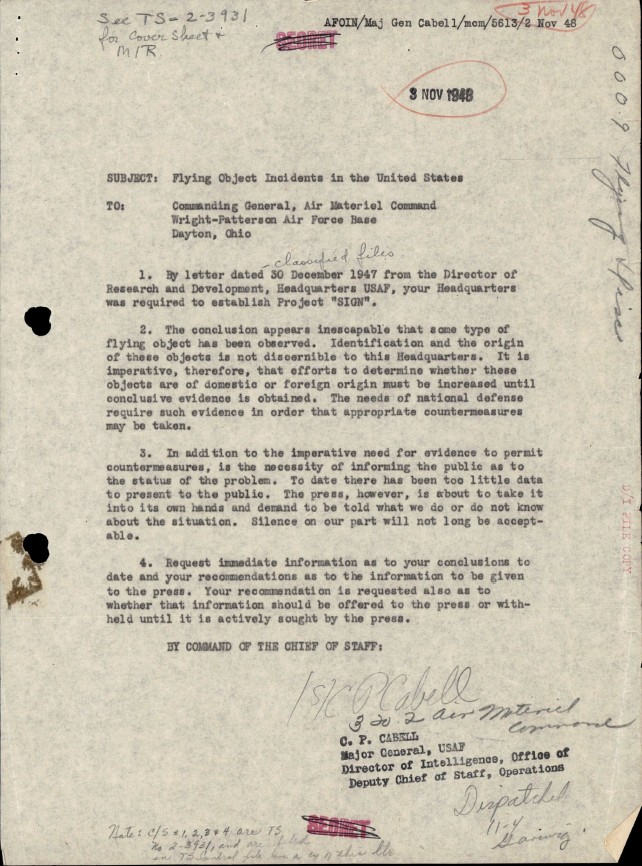
DOW-UAP-D100, Air Materiel Command Report on Unidentified Flying Objects, 1947-1948

65_HS1-834228961_62-HQ-83894_Section_004

DOW-UAP-D154, Transcript of a Presentation by Captain Edward J. Ruppelt, 1952
DOW-UAP-PR160, Presentation by Captain Edward J. Ruppelt, 1952
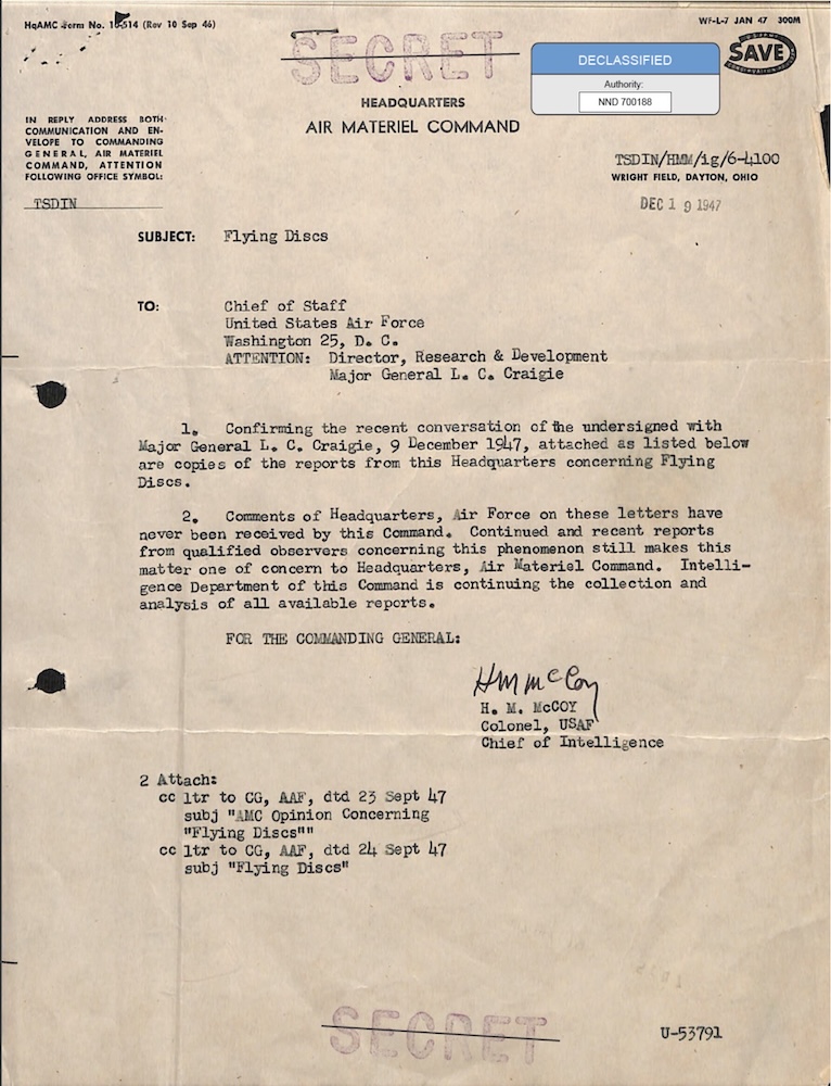
18_100754_ General 1946-7_Vol_2
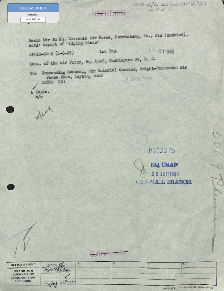
18_6369445_General_1948_Vol_1
Casos relacionados

Carta OVNI a Kenneth Arnold: isla Catalina, 1949
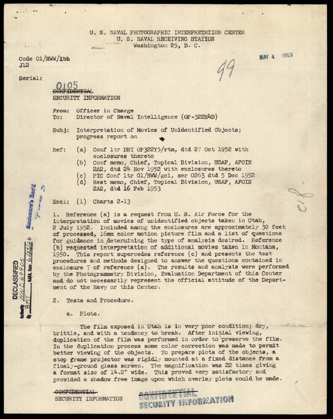
Análisis naval de películas OVNI, Montana y Utah, 1953

Cohetes fantasma sobre Suecia: informe OVNI, 1947
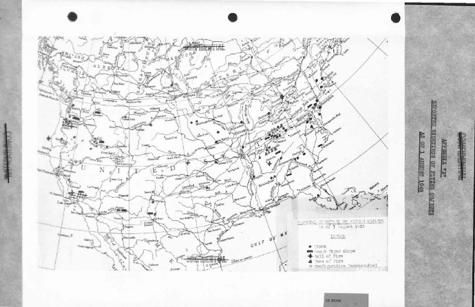
Estudio de la Fuerza Aérea sobre OVNI en EE. UU., 1948
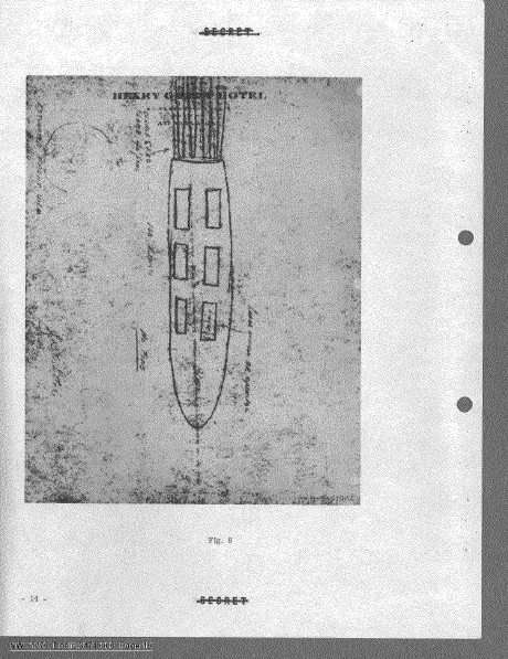
Estudio de la Fuerza Aérea sobre OVNI en EE. UU., 1949
Misma serie de expedientes

Informe de misión OVNI, Golfo Pérsico, 2020

Informe de misión OVNI, Golfo Pérsico, 2020

Informe de misión OVNI, Golfo Pérsico, 2020

Informe de misión OVNI, Golfo Pérsico, 2020

Informe de misión OVNI, Golfo Pérsico, 2020

Informe de misión OVNI, Yibuti, 2025
Mismo periodo
Estudio de la Fuerza Aérea sobre OVNI en EE. UU., 1948
Informe de inteligencia de la USAF sobre OVNI, 1948
OVNI: bolas de fuego verdes, Sandia y Los Álamos, 1948-50
Proyecto Sign: archivo OVNI Flying Discs, 1948
Misma publicación
Conferencia de Los Álamos sobre OVNI, 1949
Estudio de la Fuerza Aérea sobre OVNI en EE. UU., 1949
Análisis de la CIA del OVNI visto desde un tren, 1955
Archivos de la USAF sobre OVNI y el disco Avro Y2, 1954-55
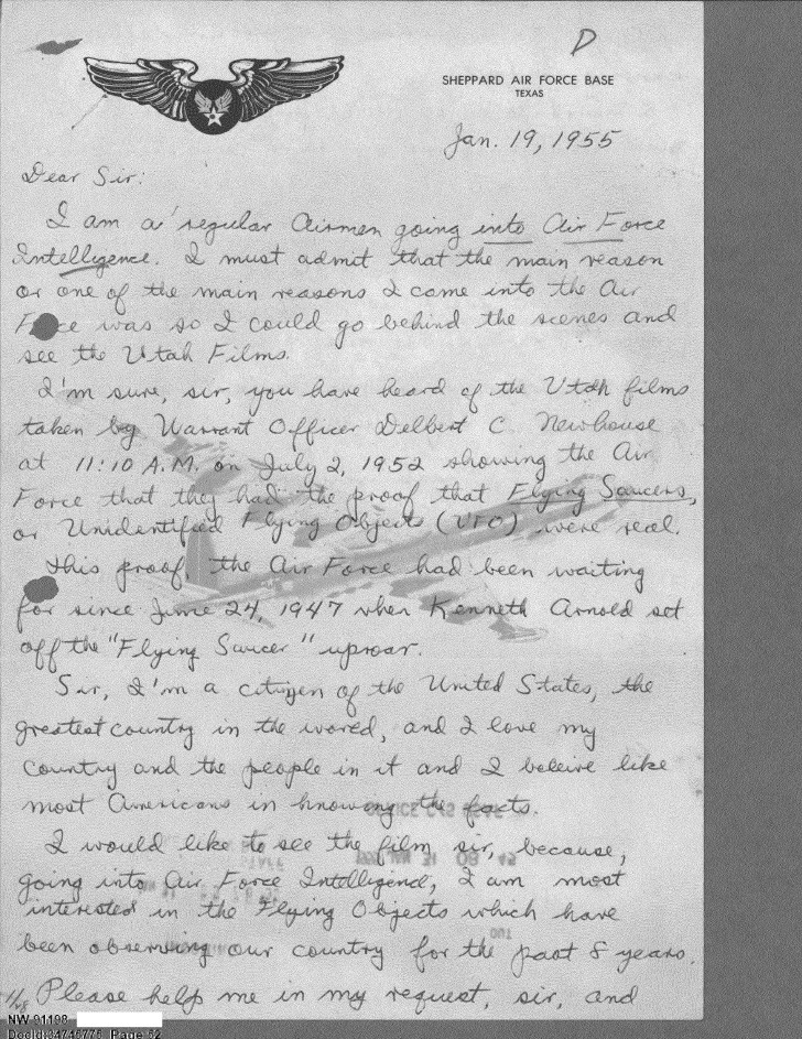
Correspondencia del Proyecto Libro Azul sobre OVNI, 1955
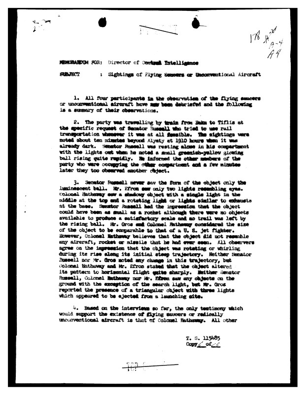
Memorando de la CIA: OVNI visto desde un tren, 1955
Misma agencia
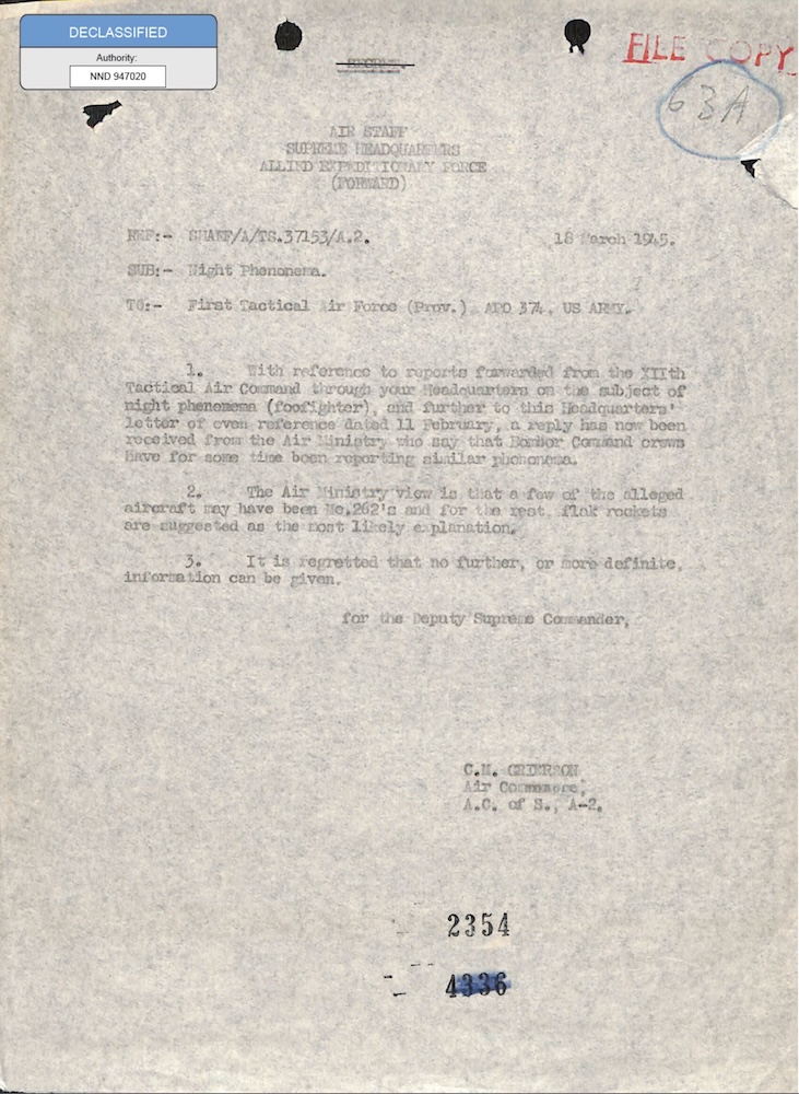
Foo fighters: archivo OVNI del SHAEF, 1945
Archivo OVNI del Proyecto Sign: Air Materiel Command, 1948
Archivo OVNI Flying Discs: carta de Twining, 1947
Cohetes fantasma sobre Suecia: informe OVNI, 1947
Carta OVNI a Kenneth Arnold: isla Catalina, 1949