DOW-UAP-D125, AAWSAP DIRD, Trägheitselektrostatische Einschlussfusion, März 2010
Kerndaten
- Offizielle Akten-ID
- DOW-UAP-D125
- Dokumenttyp
- Dokument
- Behörde
- Department of War
- Veröffentlicht in
- R06 · 2026-09-18
- Datum des Vorfalls
- 3/10/10
- Ort des Vorfalls
- Las Vegas, Nevada
- Koordinaten
- 36.1674263, -115.1484131
- Lesbare Seiten
- 72/72
- VIRIN
- 260918-D-D0360-1114
Offizielle Beschreibung
Dieses DIRD gibt einen Überblick über die trägheitselektrostatische Einschlussfusion (IEC), ein relativ unkonventionelles Fusionskonzept, das zum Einschluss von Ionen elektrische Felder anstelle der etablierteren magnetischen oder laserbasierten Ansätze nutzt, und behandelt sowohl die zugrunde liegende Physik als auch die mit dem Konzept verbundenen experimentellen Arbeiten. Der Bericht betont, dass IEC kurzfristig als kompakte Neutronen-, Protonen- oder Röntgenquelle sowie als Plattform zur Untersuchung experimenteller Fusionsansätze von Wert sein könnte, während er zugleich ambitioniertere Möglichkeiten wie aneutronische Energieerzeugung und Antriebsanwendungen darstellt. Gleichzeitig macht er deutlich, dass das Konzept von einer praktischen Fusionsenergie noch weit entfernt war, wobei experimentelle Geräte mehrere Größenordnungen unterhalb des Breakeven-Punkts arbeiteten und wesentliche ungelöste Probleme in Bezug auf Einschluss, Verluste, Gitterschäden und Skalierung bestanden. Insgesamt behandelt das Dokument IEC als einen technisch interessanten, aber weiterhin hochspekulativen Weg zur Fusionsenergie, während es nahelegt, dass ihre begrenzteren Nebenanwendungen kurzfristig plausibler waren als ihre langfristigen Anwendungen zur Energieerzeugung oder als Antrieb.
Über diesen Dokumenttyp
Bei diesem Dokument handelt es sich um ein Defense Intelligence Reference Document (DIRD), ein technisches Referenzformat, das von der Defense Intelligence Agency (DIA) verwendet wird, um Basiswissen zu einem bestimmten Thema für die spätere analytische Nutzung zu erfassen. DIRDs sind am besten als Referenz- und Synthesewerke zu verstehen und nicht als Originalforschung. Es ist eines von 38 DIRDs, die im Rahmen des Advanced Aerospace Weapon System Applications Program (AAWSAP) zwischen 2009 und 2011 erstellt wurden. Da der Anwendungsbereich von AAWSAP eine breite Palette von Nebenthemen zuließ, betrifft nicht jedes DIRD der Serie unmittelbar Luft- und Raumfahrtsysteme oder die Bewertung zukünftiger Bedrohungen. Die folgende Zusammenfassung spiegelt den Umfang und die Ausrichtung des DIRD zum Zeitpunkt seiner Abfassung wider und sollte nicht als aktuelle Bestätigung der darin behandelten Konzepte verstanden werden.
Zum Glossar →✦ KI-Zusammenfassung
Dies ist ein Defense Intelligence Reference Document (DIRD) mit dem Titel „Inertial Electrostatic Confinement Fusion" (DIA-08-1003-006), datiert auf den 10. März 2010, erstellt von der Acquisition Support Division (DWO-3) des Defense Warning Office der Defense Intelligence Agency im Rahmen der Berichtsreihe des FY2009 AAWSA Program. Der Autor ist nur als geschwärzte Kennung „AAP Person 70" angegeben. Es ist ein physikalisch-ingenieurwissenschaftlicher Überblick über die Fusion durch inertiale elektrostatische Einschließung (IEC) — einschließlich des Bussard-HEPS/Polywell-Konzepts und des Penning-Trap-Ansatzes —, mit starkem Schwerpunkt auf Arbeiten an der University of Illinois Urbana-Champaign. Es behandelt Hintergrund und Funktionsprinzipien der IEC, ausgewählte Laborexperimente, alternative Geometrien einschließlich eines zylindrischen IEC-Strahltriebwerkkonzepts, unterstützende Theorie (Struktur des Potentialtopfs, Stabilität, Energiebilanz) sowie potenzielle Anwendungen: Neutronen-/Röntgenquellen zur Landminen- und Sprengstofferkennung sowie Raumfahrtantrieb. Es behandelt die aneutronische Wasserstoff-Bor-(p-11B-)Fusion, die die Neutronenstrahlung verringern könnte, und schließt mit dem Vorschlag eines Breakeven-Demonstrationsexperiments mit 12 Ionenkanonen unter Verwendung einer Wasserstoffplasmasimulation. Der Bericht verzichtet aus Gründen der Lesbarkeit auf Gleichungen und stellt fest, dass aktuelle Geräte vier bis fünf Größenordnungen unter dem Energie-Breakeven liegen; er kommt zu dem Schluss, dass es keine grundlegenden „Show-Stopper" gibt, die Finanzierung jedoch das Haupthindernis darstellt. Das Dokument ist ein Überblick über Fusionsphysik und behandelt kein UAP. Gekennzeichnet als UNCLASSIFIED//FOR OFFICIAL USE ONLY.
Mit KI aus der Originaldatei erstellt — kann Fehler enthalten.
▸Transkript(72 von 72 Seiten lesbar)
[PAGE 1] UNCLASSIFIED/ /POI\ OPPl@IAL ~SE 8Ptl¥ Defense Intelligence Reference Document Acquisition Threat Support 10 March 2010 ICOD : 1 Decem ber 2009 DIA-08- 1003-006 Inertial Electrostatic Confinement Fusion UNCLASSIFIED/ /FOA OFFIGial.k Wli& OP•k¥ [PAGE 2] UNCLASSIFIED/ }F8R 8FFl&IAL W&& 8flki\f Inertial Electrostatic Confinement Fusion Prepared by: Acquisition Support Division (DW0-3) Defense Warning Office Directorate for Analysis Defense Intelligence Agency Author: AAP Person 70 Administrative Note COPYRIGHT WARNING: Further dissemination of the photographs in this publication is not authorized. This product is one in a series of advanced technology reports produced in FY 2009 under the Defense Intelligence Agency, Defense Warning Office's Advanced Aerospace Weapon System Applications (AAWSA) Program. Comments or questions pertaining to this document should be addressed to !AAP Person 1 I AAWSA Prog ram Manager, Defense Intelligence Agency, ATTN: CLAR/DWO-3, Bldg 6000 , Washington, DC 20340- 5100 . ii UNCLASSIFIED//liQA QFfilGIAk W&E 8HL?f [PAGE 3] UNCLASSIFIED/ ,'FOR OFFIElIAk WSE OPtklf Contents Preface ................................................................................................................. vii Section I. IEC Background and Basics .................................................................... 1 IEC Background ....................................................................................... ,.,1••········· 3 IEC Basics ............. .............................................................. ................................ 5 Bussard HEPS (or Polywell) Concept ............................................................ 10 Barnes Nebel Penning Trap .......................................................................... 10 Nebel POPS Device ..............................................................................,......... 10 Miley's "Ion Injected" Device ....................................................................... 11 Closing Remarks ......... .......... ................................................................... 11 ,,, •••••• 12 References ...................................................................................................... 13 Section II. Select Experiments ............................................................................. 14 Closing Comments ............................................................................................ 20 References ...................................................................................................... 20 Section III. Other Geometries .............................................................................. 21 Cylindrical IECs ............................................................................................... 21 Electrically-Driven IEC Jet Thruster................................................................... 22 Relation to Other Prior Thrusters ................................................................. 23 JET Extraction From a Spherical IEC ............................................................. 24 Description of the IEC Jet Thruster ............................................................. 24 Comparison to a Conventional "Plasma" Thruster ........................................ 24 Jet Extraction .............................................................................................. . 26 Experimental Jet Design and Performance ................................................... 26 Scale-up to p- 11 B IEC Space Power Unit/Thruster ........................................ 28 The Dipole Assisted IEC (DaIEC) .................................................................. 29 DAIEC Experiments .......................................................................................... 30 Khachan's Studies at U of Sydney .................................................................... 31 Concluding Remarks......................................................................................... 32 References ........................ . ..................................................................... 11 • • • • • • • • • 32 iii UNCLASSIFIED/ ,CFOA OFFIQIAk Wliii 01\lk¥ [PAGE 4] UNCLASSIFIED/ }FOA OFFICl.'1.k W&li Ol\lk¥ Section IV. IEC Theory ......................................................................................... 34 Potential Well Structure ................................................................................... 38 Tzonev et al. - Deep Well Study ....................................................................... 39 Momota et al. - Study of Virtual Electrode Strudure ........................................ 41 Kim - Stability Analysis .................................................................................... 41 Rider - Energy Balance Study .......................................................................... 43 Neutron Source Simulations ............................................................................... 44 References ....................................................................................................... 46 Section V. Potential Applications .......................................................................... 46 Neutron/proton/Xray Sources ............................................................... ......... 46 Integrated X-Ray /Neutron Sources ................................................................ 47 Nuclear and Chemical Explosive Detection Techniques ................................ 47 Overview for Weapons/Nuclear Material Simulation Articles ............. .......... 48 Pulsed Power for the Inspection Station ............................................. ......... 49 Design of the Total Integrated Interrogation System ................................... 50 Detector Array and Analysis System ............................................................ 52 Space Propulsion .............................................................................................. 54 Magnetically-Channeled Spherical IEC Array (MCSA) Concept ......................... 56 Recirculation of Radial Belt Cone Losses ..................................................... 57 Retrapping of Axial-Loss Particles................................................................ 58 Concluding Remarks ........................................................................................... 59 References ................................................................................................ ........ 59 Section VI. Possible Next Step Breakeven Experiment ......................................... 60 Demonstration of Net Energy Gain using IEC Aneutronic Fusion ...................... 60 Vision of a Future p- 11 8 Fusion Plant .......................................................,......... 61 Proposed Breakeven Experiment...................................................................... 62 Concluding Remarks ......................................................................................... 64 iv UNCLASSIFIED/ /FOA OFFICIAk Wlili 0PU:?f [PAGE 5] UNCLASSIFIED/ ,SFOA OFFI&IAk WSE 8Ptklf Figures Figure 1.1. An UIUC Spherical IEC .............................................................................. 1 Figure 1.2. Idealized Potential Structure Calculated by Hirsch for Monoenergetic Ions With No Angular Momentum ......................................................... 6 Figure 1.3. Discharge Modes in Gridded Devices Identified by Miley ...................... 9 Figure 1.4. Photo of Star Mode Seen Through a Reaction Vessel Port Window ....... 9 Figure 1.5. Schematic of the UIUC RF Gun Injector for IEC Experiments .... .......... 11 Figure 1.6. RF Gun Attached to an IEC Chamber in the UIUC Laboratory .............. 12 Figure 1.7. Photo of Center Spot Formation ......................................................... 12 Figure 2.1. The "Historic" Early IEC Ion Injection Experiment ............................. 14 Figure 2.2. Neutron Rates Measured With the IEC: Neutron Rates Measured With the IEC of Figure 2.1 Exceeded 10 9 DT n/s at 150 kV ......................... 14 Figure 2.3. Photograph of a STAR Mode Discharge ............................................... 16 Figure 2.4. IEC Landmine Detection Project at Kyoto University .......................... 17 Figure 2.5. Scheme for Landmine Detection Using a Hybrid Magnetron Type IEC Neutron Source ............................................................................ 18 Figure 2.6. 3 He Ion Source for Use in 3 He - 3 He Fusion Rate Studies at the U Of Wisconsin .................................................................................... ........ 19 Figure 3.1. Two Types of Cylindrical IECs ............................................................. 22 Figure 3.2. Jet Operational Mode in Experimental IEC Device and Jet Set-Up ...... 24 Figure 3.3. Illustration of the IEC Jet Thruster Experiment Showing Central Grid and Two Jet Grids ....................................................................... 27 Figure 3.4. Dipole Reactor Propulsion Scheme ..................................................... 29 Figure 3.5. Dipole Magnetic Field and Layout of Devices ...................................... 30 Figure 3.6. Electron Density Vs. Dipole Magnet Field Strength at 25mtorr, 20mA 31 Figure 4.1. Cross Section of the Experimental Layout of the PFX-I Experiment .... 34 Figure 4.2. Detail of the Anode and the Ion Injection Port in PFX-I ..................... 35 Figure 4.3. Plot of the Q-Value ............................................................................. 37 Figure 4.4. Sketch of Two Opposite Limits of the Beam-Maxwellian Equilibrium .. 38 Figure 4.5. The Definition of the Double Well Depth ............................................. 39 Figure 4.6. The Definition of the Parallel and Perpendicular Velocities at the IEC Cathode Grid ...................................................................................... 39 Figure 4.7. The Double Well Potential Calculated With IXL Code ......................... 40 Figure 4.8. Ion Density Profile for Potential Well ................................................. 40 Figure 4.9. The D-D Fusion Reaction Rate Versus Cathode Current ..................... 40 Figure 4.10. Plot of Growth Rate of Spherically Converging/Diverging Ion-Beam Instability......................................................................................... 42 Figure 4.11. Diagram Showing Equipotential Surfaces of the IEC Cathode Grid .. 45 Figure 4.12. Results for Calculations for Ion Energy Distributions 1 st Pass ......... 45 Figure 5.1. Block Diagram of the IEC Pulsed Power System ................................. 49 Figure 5.2. Schematic (View From Top) of a Broad Coverage IEC Inspection System for Luggage Inspection ··············································••11••······· Figure 5.3. Further Illustration of the Integrated System for Airport Luggage 51 Inspection ........................................................................................... 53 Figure 5.4. Further Illustration of the Integrated .System for Ship Container Inspection .......................................................................................... 53 Figure S.S. Image of a Fusion II Spaceship, a 750-MWe IEC Fusion-Powered Manned Spacecraft With Ion Thruster Propulsion ............................. 54 Figure 5.6. Scale Schematic of Fusion Ship II, a 750-MWe IEC Fusion Spacecraft .......................................................................................... 55 Figure 5.7. Illustration of a Three-Unit MCSA Device............................................ 57 Figure 5.8. Diagram of Belt-Cusp Fields and Particle Recirculation ............ ........... 57 V UNCLASSIFIED/ ,CFOA OFFI&IAk WSE 8PtLY [PAGE 6] UNCLASSIFIED/ /FOR 8ffl@IAL t.1!11!! eHLY Figure 5.9. Axial Magnetic Field Strength Along Two-Unit MCSA Centerline ......... 58 Figure 5.10. Diagram of Direction Randomization (KAM Effect) Due to the Magnetic Field Null Region in the IEC ............................................... 59 Figure 6.1. p- 11 B Fusion Cross Section Energy Requirements ............................... 62 Figure 6.2. IEC System With Radio Frequency Ion Gun ....................................... 63 Figure 6.3. Multiple Ion Gun Concept ................................................................... 63 Figure 6.4. Differentially Pumped RF-Driven Ion Gun ........................................... 63 Tables Table 3.1. Estimated Performance Parameters or the IEC Ion Thruster ..... .......... 28 Table 4.1. Comparison of Analytical and Numerical Estimates of Q-Values in a Beam-Dominated Solution -- for a SO-kV Square Well ......................... 32 Table 5.1. Three Kinds of Techniques Previously Used in Explosives Detection System ................................................................................................. 48 Table 5.2. Comparison of IEC Design and Magnetic Fusion Design ....................... 56 vi UNCLASSIFIED/ /FOR OFFl@IAL l?ISE O,.L\f [PAGE 7] UNCLASSIFIED/ fFOA QFFIEIAL ~81: 8HLY Inertial Electrostatic Confinement Fusion Preface This report is intended to provide the reader with an overview of the basics, current experimental status, supporting theory, and potential applications of inertial electrostatic confinement (IEC} fusion. Emphasis is placed on work in these areas at the University of Illinois Urbana-Champaign, although some other research is brought in. The report shows that IEC is a unique approach to fusion in that it offers a number of "spin-off" applications, such as a small neutron source for neutron activation analysis on the route to fusion power. The report further shows that IEC is one of the few potential fusion approaches that can potentially burn aneutronic fuels like p- 11 B (hydrogen - Boron 11). In aneutronic fusion, neutrons carry no more than 1% of the total released energy, greatly reducing problems associated with neutron radiation. That ability, combined with its simple mechanical structure and small size, make the IEC reactor, if achieved, an ideal fusion power unit. Present experimental devices are four to five orders of magnitude below breakeven (energy out/in = 1) energy gain for p- 11 B. However, it is argued that the ability to study the physics in very-small volume plasmas makes it possible to rapidly investigate scale-up to a power producing device. As an example, the report concludes with a conceptual experiment proposed for demonstration of breakeven conditions for p- 11 B using a hydrogen plasma simulation. The author has purposely tried to avoid use of ,e quations in this report to enhance readability and to stress concepts rather than analysis. However, considerable analysis is provided in a number of the source references cited. vii UNCLASSIFIED/ fFOA OFFICI.IJ.k Wii Ol\lk¥ [PAGE 8] UNCLASSIFIED/ ;CfOA OFFI&IAk WSE 8Ptklf Section I . IEC Background and Basics Before considering detail, it is helpful to obtain a rough idea of how inertial electrostatic confinement (IEC) fusion works. Gas Feed Line High-Volugc Power Supply -l- Figure 1.1. An UIUC Spherical IEC. The plasma discharge betwee·n the grid and vacuum wall creates an Ion source that is extracted and directed towards the center by the high ly charged negative grid. A photograph of a typica l IEC chamber is shown in the center. A photograph of the discharge through the view port shows the "Star Mode" discharge where ion beams are created that pass t hrough the grid openings. This is Important for long run times si nce ion bombardment of the grids, hence grid wire sputtering , is minimized. For this purpose the experimental IEC device of Figure 1.1 is considered. As shown, this "gridded" type IEC has a spherical mesh grid suspended on a high voltage feed-through in the center of a metal vacuum vessel. The fusion "fuel", e.g. deuterium gas, is first fed into the chamber originally prepared at high vacuum, e.g. 10-7 Torr. The fuel gas brings the pressure up into the 10's of Torr region. Then the voltage on the grid is raised into the many (-) kV range, creating a plasma discharge between the high voltage grid and chamber wall (electrical ly grounded). The high negative voltage on the grid serves to extract the ion from the plasma, accelerating them towards the center of the grid where in principle they interact and fuse. In practice however, the scattering cross section is larger than the fusion cross section. Thus many ions scatter without reacting (fusing). Many "near misses" essentially pass straight through the center of the plasma core and exit. This dominance of scattering over fusion reactions is the central issue of all fusion confinement approaches, forcing use of strong confinement so the ions have many passes and hence a good probabi lity of fusing before being lost from the fusion reaction chamber. In the IEC multiple passes occur because the ions are trapped in a potential "well" created by the buildup of positive charge due to the large flow of the accelerated ions into a small "core" region in the center of the negative grid. Viewed in another way, the ions extracted from the region between the grid and the wall can scatter and pass back through the grid, but can only return to the same potential surface they were born on. Thus they cannot reach the vessel wall, but instead lose their kinetic energy, stop, and are accelerated by the grid potentia l back into the center of the grid. This then provides many "recirculations" through the center of the grid volume where they have a finite probability of fusing. If not for the existence 1 UNCLASSIFIED/ / EAR OFFI CI OLi !liF QN L¥ [PAGE 9] UNCLASSIFIED/ /P"Olt OP"P"lelAL tt!I!! er•tY of various loss channels such as hitting the grid, charge exchange, or up-scattering in energy, the ions would be prematurely trapped in the potential well until they fused. The conventional requirement for fusion confinement is given in terms of the confinement parameter, nt, where n = the ion density and t is the confinement time. Also the ion energy (or temperature T) must be in the 20 or more keV range assuming D-T fuel. For breakeven, J. Lawson developed his famous "criterion" nt = 10 14 cm·3 -sec at T > 15 keV for DT fusion. Here t = energy confinement time, sec; n = ion density, cm ·3 and T = ion "temperature" or average energy. The Lawson criterion is independent of the confinement method, but does depend on the fuel via the selection of cross sections in the derivation. Magnetic confinement is generally limited to n ~ 10 14 cm· 3 by pressure balance. Then a confinement time • of~ 1 sec is required. For Inertia Confinement Fusion (ICF) or "laser fusion", compression of targets can achieve n N 10 24 , so a confinement time of only 10-10 sec is need (corresponding to the disassembly time of the compressed target). (For a general review of energy breakeven requirement for D-T fusion and other fuels like D- 3 He and p- 11 8, the reader referred to: G. Miley, Fusion Energy Conversion, American Nuclear Society, La Grange, IL 1973). Now consider the IEC. In principle, the ions focused on the center of the IEC can ~ achieve a density of n 10 16 , giving a required confinement time of 10- 2 sec for DT fusion breakeven. This time can be restated in terms of the number of ion recirculations in the IEC potential well by dividing the well diameter by the average velocity of the recirculating ion. In later cases discussed in this report, this number is typically quite large, usually N1000 recirculations. Achievement of this large number of recirculations requires strong reduction of all of the loss channels noted earlier. Grid losses can be reduced by STAR mode operation discussed later where the recirculating ions possess beam -like trajectories passing through the center of the grid opening. The ideal, however, is the elimination of the grid altogether which can be done via formation of virtual potential structures, originally proposed by Farnsworth and discussed in following sections. The temperature requirement also leads to a fundamental difference in the IEC physics vs. other confinement approaches. (Note that "temperature" is not a proper term here since it implies an equilibrium distribution while the IEC is far from that with its beam-like ions. Thus, the reader should view "temperature" as meaning average energy of the ions. In doing that, however, it is assumed that the ion energy distribution is known so that averaging is possible). Most ions in the IEC are born near the chamber wall so are accelerated to an energy close to the applied voltage on the grid during the extraction process. A reasonable estimate is that the ions reaching the fusion region in the center have an energy near 80 percent of the grid voltage on average. Thus it becomes relatively easy to achieve the Lawson D-T requirement by applying a voltage of~ 25 kV. In fact most IEC neutron sources discussed later operate at voltages > 80 kV to get into an energy range giving a higher fusion cross section. In sharp contrast, magnetic fusion devices struggle to obtain a temperature in the 10 keV range since the entire plasma population must be heated (vs. direct ion acceler ation in the IEC) due to the equilibrium distribution maintained in these plasmas. Another very important point is that Lawson assumed that the ions and electrons were in thermal equilibrium, at the same temperature, T. This is a reasonable approximation for magnetic confinement, but not so for the IEC. In the latter, the electrons form a "distorted" Maxwellian distribution at an effective temperature well below that of the 2 UNCLASSIFIED/ /FOR &FFICI0~ 1155 AN! X [PAGE 10] UNCLASSIFIED/ /POI\ orr1e1At li!II!! OHL¥ beam-like ions. Since electron energy loss processes such as radiation emission are serious, the Lawson temperature criterion must be modified for the IEC. A first rough estimate is the Te/T1< 1/3 for DT. (Here T1and Te are the ion and electron "temperatures", respectively). Control of th is ratio is a complex physics issue, involving the relative ion and electron source rates and energies and the potential well structure. In later sections use of p- 11 B (hydrogen-boron-11) fuel in the IEC is considered. This is very attractive since it provides all charged particle reaction products, making this an unique "aneutronic" system. Such a reactor represents a truly ideal system from an environmental and energy sustainability perspective. However, for such fuels, t he Larson criterion becomes much more demanding, increasing nT by two orders of magnitude and T to 150 kV. Also, for the IEC, a Te/T1< 1/9 becomes essential. (Using temperature ration is a very simplified representation. The radiation losses are quite sensitive to deviation in the actual energy distribution of the ions and electrons . For example, electron Bremsstrahlung emission primarily comes from the high energy "tail" of the electron distribution while energy transfer with ions is dominated by the "foot" of the electron distribution. At high powers, interactions in these regions can become quite non -linear, depleting or "burning out 0 the local populations in these regions. This effect causes energy losses to saturate, hence can be quite beneficial under some circumstance . However, the phenomenon is complex to evaluate numerically, so little has been reported on it for IECs to date). The very aggressive p- 11 B Lawson requirement is employed in the design of the breakeven experiment of Section VI. While this discussion of IEC physics has been greatly simplified, it hopefully provides more insight into the basic concepts and issue before delving into more detail. IEC BACKGROUND Inertial Electrostatic Confinement (IEC) was conceived of by Philo Farnsworth, the inventor of electronic television, as an approach to fusion power using electrostatic fields for confinement (Reference 1.2). When he did this in 1955, the prime approaches being pursued worldwide were magnetic confinement or inertial (laser compression of targets) confinement. In fact, electrostatic confinement had been written off by most scientists due to Earnshaw's theorem (Reference 1.4) which stated that plasma could not be confined by electrostatic fields alone. That was simply an expression of the fact that use of a biased plate to confine one species, say ions, would automatically attract the opposite species, electrons, such that the whole plasma would transport to the plate. Farnsworth seemed to intuitively understand that this theorem assumed steady state, so that if, as in IEC, the ions were dynamically moving and confined, they would electrostatically confine the electrons. Farnsworth went further and realized that in a spherical system virtual electrodes would form a high density plasma region if the confined ions were focused at the center of the sphere (Reference 1.2). While Hirsh worked with Farnsworth to demonstrate early experimental success with IEC experiments (Reference 1.2), the concept passed from view as magnetic and inertial confinement resea1rch exponentiated. Then in the late 1990s R. W. Bussard revived the concept with the hybrid IEC magnetic approach (Reference 1.6- 1.7). In this approach the electrons were confined in the magnetic field, forming a potentials trap for ions. [Note the similarity to the original conceptual potential well discussed by Elmore, et al. (Reference 1.1)]. Upon invitation by R.W. Bussard to join this effort, the author, George Miley, undertook supporting experiments that were a variation of the original 3 UNCLASSIFIED/ /EAR OFFICIO! !!SF ON! X [PAGE 11] UNCLASSIFIED/ /FOR OFFI&IAk W&E 8Ptklf Hirsch approach, using electrostatic grids to form a t rap with ions that then brought electrons in. He realized that this approach could result in a very attractive low level neutron source for neutron activation applications, and began that development. Such work was soon taken up in several other laboratories, including Los Alamos Nationa l Laboratory (LANL), University of Wisconsin and Kyoto University. Meanwhile Bussard's work continued with strong funding from the military. However, little was published or known about this until 2008 when he made public appeals on "YouTube" to regain funding stopped just when the experiment achieved a major success. Subsequ,ently, funding resumed but R. W. Bussard passed away shortly thereafter due to a long battle with cancer. His company and work were then taken over by R. Nebel who took leave from LANL to undertake this new work. That effort is now in progress and represents the largest IEC power oriented project in the US or elsewhere (but still modest with a half dozen senior scientists involved). Meanwhile, laboratories elsewhere working on IEC neutron sources have continued while the U of Wisconsin has added an IEC proton source as an option using sim ilar technology. The labs, including the UIUC, have fusion power as an ultimate goal, but must focus on their funded near-term "spin-off" projects. At this point the IEC still receives no funding from DOE which remains focused on the Tokomak route to fusion power. Thus, with little funding, slow progress has been made in answering the key question of whether or not the IEC can be developed for fusion power. If it can, the device would be simpler and smaller than a Tokamak, malking it an extremely attractive option. In addition, its beam - like reactions (highly non-Maxwellian) make the IEC very well suited for burning alternate ("advanced") fuels like D- 3 He and p- 11 B which are much more environmentally favorable than conventional DT fusion . Unfortunately Tokomaks are not well equipped to go forward to such fuels. On the other hand, the use of non-power-producing IECs for other applications, such as sma ll neutron, proton, and x-ray sources, has been .amply demonstrated. Now, the issue is how well and in what applications the IEC sources compete commercia lly with other options such as accelerator target sources. This report is intended to provide the reader with important insight into the physics and technology of IECs relative to both power and neutron/proton/x-ray sources. With this background, hopefu lly the reader can formulate an opinion about the potential for IEC applications. Due to the limited funding for IEC research to date, much more has to be done to actually demonstrate its application, especially for power production. Thus that opinion must remain a personal one for the reader. One other limitation of this report is that it largely provides details based on the author's work on IECs over the last decade. Thus it will not do justice to the ongoing work by others, notably at EMC 2 on the Bussard Polywell device or the advanced gridded IEC neuron/proton so urce development work at the U of Wisconsin, Kyoto University, and Tokyo Institute of Technology. Some insight into these efforts is given in comments and in references supplied, but t he reader is encouraged to discuss that work with those individuals directly. 4 UNCLASSIFIED/ /POI\ 0rr1e1At l?ISE 8Ptklf [PAGE 12] UNCLASSIFIED/ /fOft Offl@IAL l!ISE 8P•tlf IEC BASICS We begin by presenting the early very basic theoretical study by Elmore, Tuck, and Watson (Reference 1.1). That addresses the key question of the fusion power density obtainable with potential well confinement. One of their basic assumptions is that the potential well is "dug" by electrons which trap ions. Certain added assumptions lead to well depth, etc, and finally they conclude that the system is unstable for ion densities sufficiently high that appreciable thermonuclear yield is expected. They qualify this conclusion saying "admittedly, a more thorough investigation is required to obtain a complete understanding of stability of this electrostatic device". This result was quite negative for electron formation of potential wells, but left the route possibly open since the subject "needed a more thorough investigation." Later, for various reasons, R. W. Bussard still pursued this concept by introducing the High Energy Power Source (HEPS) Polywell device which uses a spherical simulated magnetic field to stabili ze the potential well formed by electrons. This represents a "hybrid" magnetic-lEC confinement system where electrons are confined by the magnetic fields, forming the potential well wh ich "traps " ions. Apparently, Bussard's view was that this added magnetic stabilization would overcome the earlier Elmore and Tuck criticism. Subsequently, some of his reports used particle-in-cell simulations to support the view that such a stabilized electron potential well would allow adequate density for attractive fusion densities. However, the next IEC experiments following the Elmore et al. analysis (prior to Bussard's) were the Hirsch-Farnsworth experiments (Reference 1.2) which used ion (vs. electron) injected traps (as does the present author's work). This selection was largely driven by the desire to gain added stability by the large momentum of recirculating ions that form the potential well. More about ion vs. electron injection routes will be covered in later sections. Next, it is important to review the multiple well ("poissors" solution) Farnsworth - Hirsch found for ion injected formation of potential wells in spherical geometry. This is described in the paper by Hirsch (Reference 1.2). As seen from Figure 1.2, monoenergetic ions with angular momentum "drag in" electrons to create "onion skin" like nested potential wells around the center of the sphere such that the ion density goes to infinity in zero volume at the origin. 5 UNCLASSIFIED/ }FOA: OFFICIAL !!ii onn X [PAGE 13] UNCLASSIFIED/ /FOR 8FFIOIAL ~81!! 9HLY 1'10 .... ----- - - ' ' - - - . . ----- - - - - . - - - - - - - - - r - - - - - - - - - - - . . . , , 10 ~ ~- - - -- - ----- - - - - - - - - - - - - - --+---- - --,t .....- iR .._o •u:s Figure 1.2. Idealized Potential Structure Calculated by Hirsch for Monoenergetic Ions With No Angular Momentum. The nested virtual anodes and cathode s observed were originally termed " poissors" by th e inventor, Philo Farnsworth . This is a very striking result that enthused these researchers to push on with this research. It, in effect, circumvents the Elmore et al. restriction by changing the potential well physics fundamentally. Of course in practice, there will be a spread in energy and angular momentum, so one would not expect more than a single potential well (vs. the infinite poissors of Farnsworth) to form in practice. The questions remaining then were (and still are): "How deep can such a well be in practice and how high an ion density can be trapped in it?" Various studies followed to study these issues more thoroughly using simulation codes. For examp le, Klevens and Black found in Reference 1.3 that: "A model of an electrostatic confinement device with ion injection has been developed which provides strong correlation between theory and experiment. The ion density profile was determined in position velocity throughout the two concentric grids by considering the processes of cha r ge transfer and grid capture. A shallow-well approximation was incorporated in the model by assuming that ions encountering charge transfer in the inner grid region were accelerated up to a maximum of 5 percent of the applied grid voltage, and that the velocity of beam ions was constant in this region. Distribution functions in total energy and angular energy were developed for both ions and electrons. The ion distribution function consisted of three parts: a beam created at the anode and accelerated by the applied cathode voltage; a low -energy group produced by charge transfer near the cathode or in the center; and a intermediate-energy group resu lting from charge-transfer reaction between anode and cathode. For each group the angular energy was assumed uniform up to a maximum value, which was different for each energy group. The electrons were assumed to be isotropic in velocity space, and to be uniformly distributed in total energy in the potential well in which they are trapped . The distribution functions were substituted into Poisson's equation and potential and density profiles for various 6 UNCLASSIFIED/ I f8R 8FFIEilAk lel&& 0PU,¥ [PAGE 14] UNCLASSIFIED/ /FOR 8FFIEJIAL ~SE er•tv experimental parameters were obtained. The parameters which were varied include the background pressure, the ratio of electron to ion circulating currents, the applied potential difference between the grids, and the inner grid variables such as measured current, transparency, and construction error. When estimates of each of these parameters which simulate the ion injection mode experiment were inserted into the model, the resulting potential profile exhibited no more than a shallow potential well. This result is consistent with that of beam defection measurements in the ion injection mode experiments. In spite of these assumptions, the model is extremely valuable in determining the relative (sensitivity of the potential well profile and depth to effects of many of the system parameters. It has been found that for the "medium" level of ion currents under discussion, the most critical factors which inhibit deep well formation are inadequate spherical focusing and charge neutralization. The focusing is determined to a great extent by the degree to which the grids are spherical potential surfaces. The grid must approach a spherical shape within a few percent before other factors such as grid transparency and background pressure play an important role. However, as the current is increased, the requirements for sphericity are somewhat relaxed. For a grid construction error of less than 5 percent, increasing the grid transparency and decreasing the pressure will also lead to significant improvement in well depth." These results were somewhat encouraging. However, they showed that grid deformation could be very harmful. This deserves several comments. First, the present author (G. Miley) later showed that design of grids with larger openings provided the STAR mode where ion beams passed through the center of the openings, avoid ing grid collisions and making sphericity of the grid itself less important. This is important for small neutron/proton source type devices . However, the assumption of grids fails to address the question of how a grid could survive in a power reactor or if they could be eliminated to use a potent ial well with virtual electrode formation. The use of grids cannot be completely ruled out for power reactors. Magnetic field protection techniques, active cooling, etc. are conceivable. Another question relates to the role of background gas in the IEC. The point is this: When Miley moved to simplify the device for small neutron sources, he used the discharge between the grid and vessel to form the ions needed for acceleration and fusion. This inherently forces use of a modest background neutral gas pressure of the fuel (typically deuterium) inside the reaction vessel. That in turn results in ion reactions with the background gas becoming a dominant process in these IECs . Such interaction includes fusion itself, scattering, charge exchange, etc. This greatly changes the plasma physics of the IEC as opposed to the ideal of a potential well with "zero" background pressure. Some key differences in the physics of such IECs were brought out by Tim Thomson in his experimental study described in Reference 1.4. He noted that: "In present gridded systems, convergence is not important since beam -target fusion reaction dominate the reactivity of these devices, as evidenced by the linear scaling of reactivity of these devices, as evidenced by the linear scaling of reactivity with the cathode current. In fact, convergence may reduce the reactivity by forming a virtual anode that limits the centr al ion density. However, this space charge effect can be overcome by proper introduction of electrons. Good convergence is required to achieve optimal beam -beam reactivity scaling for the application that require higher fusion reaction rates, and the importance of symmetry in determining convergence places a 7 UNCLASSIFIED/ /P"Olt 8FFIEJIAk Wliii QrslL¥ [PAGE 15] UNCLASSIFIED/ /POI\ OPPl@IAL ~SE &PU:¥ constraint on any Spherical !EC device planned for these applications. The observed loss of convergence with decreasing pressure and increasing current makes achieving significant beam -beam scaling far less favorable ." In add ition to the issue of beam -background fusion dominating in the gridded systems at higher pressures, Thomson pointed out the importance of energetic ions undergoing charge exchange and being lost from the system. This work and others on the small gridded systems at that time showed several important problems which are best understood by considering beam-background vs. beam -beam fusion scaling. The former scales with density and pressure as nb • nok <av> ~ lilb • p <av> while beam-beam fusion goes as nb2 <av > . Here: nb = beam ions per cm 3 ; nbk= background atoms per cm 3 ; p = background pressure; <av> is the fusion reactivity averaged over the appropriate beam background (or beam-beam) distribution functions. If ions are produced as done in most small gridded experiments by electron ionization collisions with neutral gas during a plasma discharge between the grid and vacuum vessel wall, reduction of background gas pressure will also reduce the ion source, reducing the reaction rate. Thus, it becomes apparent that to get the favorable beam beam scaling needed to go into the power reactor regime, ions must be produced externally while the main reaction chamber is keep at very low background pressure to avoid charge exchange losses. Indeed, without explaining that this was the reason, Hirsch used external ion '\guns" in his early experiment at Farnsworth labs. The present author (G. Miley), however, went back to the internal discharge ion source technique to simplify the device for portable neutron source appli,cations. Power devices will need to go back to external production of some type however. Again, this issue will be addressed further later. While earlier workers sought small grid open ings designed to provide uniform ion flows for good core plasma convergence (stressed in the earlier papers already noted), Miley disclosed in a paper in Reference 1.5 that the STAR mode could be produced with wider grid openings. In fact, Miley noted that three key modes can be formed in gridded IECs depending on the pressure and grid openings. These are described as: "Glow discharge operation of the IECGD is categorized by three distinct discharge "modes": Star, Central Spot, and Halo (illustrated in Figure 1.3). These names are quite descriptive of the visual appearances of the visible light emitted from the discharges. All three modes are reproducible and stable; each is associated with a different potential well structure, hence neutron production rate. The star mode was used extensively in recent experiments. It is distinguished by microchannels or "spokes" radiating outward from a bright center spot (Figure 1.4). As verified by magnetic deflection experiments, the spokes are primarily composed of ion beams aligned so that they pass through the center of the openings delineated by the grid-wires. This mode is very efficient for neutron production, since the large effective grid transparency allows numerous passes of ions through the center spot before being intercepted by the grid or being ion by charge exchange. The Star mode is typically obtained at lower operating pressures (<10 mTorr) and higher voltages (>30 kV), using a carefully formed grid with good sphericity and high transparency (>95 percent). The halo (or "jet") mode occurs when one of the grid openings is slightly enlarged compared to the others." 8 UNCLASSIFIED/ )FOA OFFIQIAk Wliii 01\lk¥ [PAGE 16] UNCLASSIFIED! /POI\ OPPlelAL ~SE &PU:¥ I , 'I , I I • I \ I I I I I ... ___ ,.,. ; , I Figure 1.3. Discharge Modes in Figure 1.4. Photo of Star Mode Seen Through a Reaction Vessel Gridded Devices Identified by Port Window Miley In summary, the basic IEC approach is to create a potential well through electrostatic confinement of one of the plasma species in a dynamic (inertial) configuration. "Inertial" effects associated with dynamic motion of the confined species are essential to avoid plasma losses predicted for systems by Earnshaw (as noted earlier). The two primary approaches can be termed, "ion injected" or "electron injected", the "injected" species being the one form in g the potential well. In order to mainta in the well, the second species brought in with the injected one must not completely neutralize the plasma, i.e., the IEC plasma is inherently "quasi-neutral". This well then provides trapping and convergence of the ion "streaming" towards the center of the trap region, forming a dense fusing plasma there. For a power reactor the objective is to obtain ion beam-beam collisions in this central core. For neutron/proton production satisfactory reaction rates can come from beam background collisions. However, this sca ling with injected current would require excessive input power for a practical power-producing unit. Thus beam-beam scaling of the reaction rate as the current squared (or higher powers as noted earlier may be possible due to nonlinear effects) is essential. The vision of a power reactor seeks a "zero" background pressure, thus generally involves an external ion source with acceleration into the trap at ultra low pressure to obtain beam -beam collisions. As described earlier, this changes the details of the physics just discussed for an ideal "zero" background pressure device. The issue of whether the trap should be formed by ion injection or by "digging a well" with electrons remains open, but involves stability and reaction volume (focusing) optimization issues. Since the discussion to here has been largely on gridded devices, we next briefly review some other approaches: the Bussard HEPS concept, the Barnes Nebel Penn ing trap, the Nebel POPS device, and the Miley ion injected device. 9 UNCLASSIFIED/ /F8R 8ffl@IAL l:t!!! or•t I [PAGE 17] UNCLASSIFIED/ / FOA OFFl&ilAk lalli& O,.klf Bussard HEPS (or Polywell) Concept In Bussard's Polywell IEC, a spherical magnetic field termed a "Polywell" is approximately obtained with a multi-pole cusp magnetic field (Reference 1.6). More about the theory of flows in this configuration is given In the paper by N. Krall (Reference 1. 7), and some stability issues are addressed in the Wang and Kral I paper of Reference 1.8. One of the key physics revolves around electron losses from the poles in the cusp field. Krall and Bussard argue that a plasma "waffle-ball" effect causes the loss cone angle to be reduced due to the high pressure developed in the IEC plasma. The issue still needs further experimenta l verification. The Polywell approach is very important and it is currently pursued by R. Nebel's EMC 2 company in Santa Fe with significant DOD funding. More insights will be provided throughout this report, but the reader is encouraged to study the reports/articles, as already explained earlier, since the present report is directed more at "ion injected" type devices studies at UIUC. Barnes Nebel Penning Trap The Penning trap concept described in Reference 1.9 is explained by Barnes et al. as: "The Penning Fusion (PF) device uses a unique plasma confinement principle. In PF, a nonneutral electron plasma is confined in a modified Penning trap by a combination of applied magnetostatic and electrostatic fields. The e!lectron space charge, in turn, electrostatically confines a minority, unmagnetized ion species. To apply such a system to fusion energy production, it is necessary to raise the applied voltages (producing the confining electrostatic field) to the order of 100 kV or greater. Even with such a high potential, in a practically sized system, the electron density (and to a greater degree the ion density) falls short of that required to give reasonab le fusion reactivity . Thus, intrinsic to PF being an interesting concept is the idea of ion focusing, either in space or time, or some other means of enhancing ion reactivity. In this way the reactivity may be greatly enhanced over that available with the background density. Penning Fusion is strongly related to the IEC, but it attempts to address two limitations of the IEC. First, following the Bussard -Krall Polywell theory (Reference 1.6, 1. 7) the grid is replaced by an electron cloud, which forms a virtual cathode. In this way, ion-grid collisions and associated limitations (such as secondary electron emission from the grid and grid heating) are avoided. Second, high rates of ion-ion collisions, which limit the theoretically achievable fusion ga in Q (fusion power/input power) to around unity are avoided to some extent with this type of well. However, issues of electron loss and cone losses, radiation damage of the magnets and cooling, and the ability to circumvent the Elmore et al. density limit remain as questions. Nebel POPS Device Theoretical studies by Barnes and Nebel (Reference 1.10) show that a small interna l oscillating ion cloud may undergo a self-simi lar collapse in a harmonic osci llator potential formed by a uniform electron background. This then forms a dynamic IEC device, but with a quite different ion distribution factor vs. the "conventiona l" beam -li ke one. A key issue for this concept is how much plasma compression can be achieved by the POPS (Periodically Oscillating Plasma Sphere) oscillations. Recent work has shown that by properly programming the distribution function of the injected electrons it is possible to significantly improve the space dynamic charge neutralization and the plasma compression. Reference 1.10 extends that pr evious work in a systematic fashion by developing a formalism that determines the required velocity distribution of 10 UNCLASSIFIED//509 OFFICI 0 l 11 ili Alll¥ [PAGE 18] UNCLASSIFIED/ /FOR 8FFI@IAL ~81!! 9HLY the injected electrons so space charge neutralizatio111 can be achieved. This formalism is then included as a boundary condition in a gridless particle code. Results indicate that although the formalism works well during the early phases of compression, when the compression gets large the solution bifurcates and becomes unphysical. Subsequent experiments on POPS at Lawrence Livermore National Laboratory (LLNL) were encouraging, but have not been continued at a high level of effort due to key staff leaving for EMC 2 . Thus, the practicality of this concept remains an open question which deserves more research. Miley's "Ion Injected" Device The key to developing a IEC power device is to use external ion "guns" to form and inj ect Ions into the spherical IEC chamber. This eliminates the need for a grid and differential pumping between the gun and chamber allows the high vacuum needed in the chamber. (Ion injection by external guns was originally used by Hirsch as already noted. Also, more recently other labs, e.g. the University of Wisconsin and University of Kyoto/Tokyo Institute of Technology, have started gun injection work. Some of that is described later in this report) . The ion formation is done in the high pressure gun discharge region outside of the chamber. Miley at UIUC (see Sections IV and VI) has been studying such a system, both theoretically and experimentally. The theoretical studies confirm that such an IEC plasma can exist stably and has sufficient confinement time for aneutronic fusion. This assumes, however, very precise control is maintained over the energy and angular momentum of injected ions and a balanced supply of electrons is provided. A radio-frequency (RF) ion injector (or "gun") capable of such operation has already been developed . A sketch of th is design is shown in Figure 1.5. magnetic focusing lens coaxial copper resonator: hollow cylindrical stainless steel flange l ceramic (insulator) upper plasma stream: floating negative potential Q~ n beam~t,,J;,l;~==;:;===l:~l=t'A'Ft,VtJil/1t:tl't~l=l:~ .l4.,._t:t,:==;=f=i=r"iF=;;:=l D2 gas feed positive wall, j l magnetic differential coils part of vacuum chamber ~ helical antenna ! glass tube RF generator lower plasma stream: floating Figure 1.5. Schematic of the UIUC RF Gun Injector for IEC Experiments 11 UNCLASSIFIED/ /FOA OFFI51Ak Wlili 0Plk¥ [PAGE 19] UNCLASSIFIED/ /FOA QFFI&IAL ~!ii: f>HLY In this RF gun, a graded index magnetic field is used to increase the ionization efficiency. A key component is the magnetic focusing lens at the extraction port. This allows very efficient differential pumping between the high pressure gun chamber and the low pressure IEC chamber. It also provides some control of the angular vellocity of entering ions. The UIUC RF ion-injector is shown attached to an IEC chamber in Figure 1.6, and a photograph of the focal spot achieved with injection from this single injector is shown in Figure 1. 7. Note that ion scattering off of the center dense plasma "core" causes noticeable (but "faint") recirculating ion beams observed in the photograph of the discharge. With additional injectors, the recirculation pattern should become quite symmetrical about the center. These studies did include differential pumping so that number of recircu lating passes, ~. by an ion was very low, roughly 2. The injected ion current, I, was about 50 mA. Still, based on measurements of neutrons emitted using deuterium fue l, the Q (fusion energy gain/energy in) was remarkable for such a small device, order of 10·6 . Based on these results, an aggressive p- 11 B breakeven experiment using this type of IEC is discussed in Section VI. Figure 1.6. RF Gun Attached to an IEC Chamber in Figure 1.7. Photo of Center Spot Formation. The the UIUC Laboratory main beam observed is a direct path along the injector angle. Other faint lig ht channels indicate beams for scattering of the central core region. CLOSING REMARKS As seen, a wealth of information has been developed in studies of gridded IEC devices. However, the beam- background fusion used in these devices involves important differences in physics compared to what is needed for future beam -beam IEC reactors. Most notable is the need to maintain an extremely low background pressure to prevent interactions with background neutrals. Further, physica l grids are subject to damage at high power levels. As pointed out, some studies show grids can survive at modest powers. But, for aggressive power units such as the p- 11 B plant of Section VI, they must be replaced with virtual electrode surfaces creating a deep potential well for ion confinement. Upscattering out of the well must be minimized while electron 12 UNCLASSIFIED/ /liOA: OlililCI0L: !Pi'li ODIL:¥ [PAGE 20] UNCLASSIFIED/ /fOft Offl@IAL l!ISE 8P•tlf temperatures are suppressed. These issues will be discussed further in Section IV on theory and Section VI on a proposed breakeven experiment. REFERENCES 1.1 W. Elmore, J. Tuck, and K. Watson, "On the Inertial-Electrostatic Confinement of a Plasma", Phys. Fluids, vol. 2, No. 3, ( 1959) pp . 239-246 . 1.2 R.L. Hirsch, "Inertial-electrostatic confinement of ionized fusion gases," J. of Appl. Phys., vol. 38, (1967) pp. 4522-4534. 1.3 W. M. Black and E. H. Klevans, "Theory of Potential -Well Formation in an Electrostatic Confinement Device", J. of Appl. Phys., Vol. 45, No. 6 (1974) pp. 2502- 2511. 1.4 T. A. Thorson, R. D. Durst, R. J. Fonck, and L. P. Wainwright, "Convergence Electrostatic Potential, and Density Measurements in a Spherical Conver gent Ion Focus", Phys. Plasmas, vol. 4, no. 1, (1997) pp. 4 -5. 1.5 G.H. Miley, et al., "Inertial -electrostatic confinement neutron proton source," Third International Conference on Dense 2-pinches, AIP Conference Proceedings 299, (1993) pp. 675-689. 1.6 R.W. Bussard, "Some Physics Considerations of Magnetic Inertial - Electrostatic Confinement : A New Concept for Spherical Converging - Flow Fusion", Fusion Technology, vol. 19, no. 2, (1991) pp. 273-293. 1.7 N. A. Krall, "The Polywell™: A Spherically Convergent Ion Focus Concept", Fusion Technology, vol. 22, nol, (1992) pp . 42-49. 1.8 S. K. Wong and N. A. Krall, "A Nonlocal Theory of Counterstreaming Ion Instability", Phys. Fluids B, vol. 5, no.6, (1993) pp. 1706- 1714. 1.9 D. C. Barnes, M. M. Schauer, K. R. Umstadter, L. Chacon, and G. H. Miley, "Electron equilibrium and confinement in a modified Penning trap and its application to Penning fusion", Phys. Plasmas, vol. 7, no. 5, May (2000). 1.10 R. A. Nebel, D. C. Barnes, Fusion Technology 38, 28 (1998). 1.11 D. C. Barnes, R. A. Nebel, "Stable, thermal equilibrium, large -amplitude, spherical plasma oscillations in electrostatic confinement devices", Physics of Plasmas 5, 2498 (1998). 1.12 J. Park, R. A. Nebel, S. Stange, S. K. Murali, "Periodically osci llating plasma sphere", Physics of Plasmas 12, (2005) 056315. 13 UNCLASSIFIED/ /FOA OFFIQIAk Wliii 01\lk¥ [PAGE 21] UNCLASSIFIED/ / FOR OFFIElIAk WSE OPtklf Section II . Select Experiments In this section some select experiments are briefly reviewed with the main focus on ion injected IECs. Beginn ing with the early Hirsch gun injected IEC experiments that are important both historically and from a physics perspective. Other experiments aimed at "spin -off" applications are then covered, followed by a discussion of severa l recent gun injection type studies. Readers interested in more detail should consult references. In Reference 2.1, Robert Hirsh disclosed experiment al results with very high D-T neutron rates from an ion-injected IEC shown if Figure 2.1. Note that six ion "guns" were used to create a low energy ion beam that entered the chamber and was trapped via electrostatic structures to form the potential well structure desired for IEC operation. However, differential pumping was not used so beam -background and charge -exchange collision must have still played a significant role in this experiment. Still Hirsch obtained "record" neutron rates for DT fusion shown in Figure 2.2. ROBERT L , HIRSCH ,010 r, /e- ·--, ' : ~ HIGH VOL.TAG[ DOME 0 CONU,INING u w 109 [g AUXIL A,tY POWER SUPPI. IES ll) .... ~ 0 Q:: t- ~ tHGH VOLTAGE INSUL. ATOA . co.I I- :, 108 0. 6 107 I- :J .z 106 .. AP PUEO POT Tl~L - V Figure 2.1. The "Historic" Early IEC Ion Injection Figure 2 .2. Neutron Rates Measured With the IEC of Experiment of R. Hirsch Working With Philo Figure 2,1 Exceeded 10 9 OT n/s at 150 kV. For Farnsworth perspective, note tha t, as discussed later, UIUC IEC gridded devices routin ely produce 10 8 DD n/s at "' 80 kV. This is sl ightly above Hirsch's result but uses higher ion currents. The key point about this remarkable result is that the neutron production rates are well about that predicted by simple beam-background fusion reactions, implying that benefit 14 UNCLASSIFIED/ / &OA: O&&ICI AL !!i i ODt11 X [PAGE 22] UNCLASSIFIED/ /fOR Offl@IAL ~SE 8,.Llf was obtained from recirculation beam-beam reactions in a potential well such as in Figure 2.1 (but without multiple structures). Indeed, to further confirm the existence of a potential well, Hirsch did both collimated neutron and gamma measures. As shown in the paper, he found structure for both consistent with well formation. One possible explanation is that the ion-electron densities obtained were high enough to "burn out" (completely ioni ze) the background neutrals in the potential well. There is no direct evidence to support this view however. These important results have never been fully explained. Attempts to reproduce his experiments were done by Gardner and co-workers at Brigham Young University (Reference 2.1) who borrowed the original device used by Hirsch. However, despite many months of effort, the neutron production they obtained was significantly lower than that reported by Hirsch. They attributed this problem to a failure to regain the gun alignment necessary to have a highly converged plasma "core" in the center of the device. A major hurdle to this appears to have been that no provision was made to allow precision alignment of the gun ions entering the device (although the investigators did not mention this explicitly). Later when Miley reinitiated gun experiments, his first gun design followed many of the design elements used by Hirsch, but incorporated electrostatic beam steering. This worked well, but the design was eve ntually discarded to move to RF guns with much higher beam currents. In addition, the gun desig n of Figure 1.5 uses a magnetic nozzle for reducing the exiting beam diameter and to allow strong differential pumping (not used in the prior Hirsch experiments). It should be stressed again here that the terms "injector" and "gun" are misleading. The objective is to simply "flow" low energy ions into the device such that they are then accelerated to fusion energies by either the grid or the virtual electrode structure. Thus, a loss of "excess" energy after injection is needed trap the ion, i.e. prevent it from simply passing through the potential well and hitting the opposite wall. A biased reflector on the opposite wall can be introduced to help prevent this, but this only works well if the entering ions have little excess energy. To further understand this problem, the reader is advised to study the design of the Hirsch chamber of Reference 2.2 which uses an auxiliary biased grid ("reflector") near the wall. Indeed the issue of how to best introduce ions into t he potential well so t hat t heir energy fa lls below that required to escape the well is a key for proper design of the IEC. In addition to designs to cause an initial ion energy loss to "drop" them into the potential well, designs with ion sourced " imbedded" in t he well such that ions are born trapped are discussed later. Gridded devices for near-term applications such as neutron activation analysis (NAA) do not rely on virtual well potential traps. Rather, the negative bias of the grid forms a potential trap, and ions are born within the potential trap by ionization collisions in the internal plasma discharge. Note that the electron injected case faces the same problem of getting ions into the potential trap. The approach used with the Polywell employs an embedded ion source plus relies on "burn out" densities to eliminate neutrals. Success with this technique, after many problems, was the key that lead to the "breakthrough" reported by R. W. Bussard (as noted earlier) just before he passed away. 15 UNCLASSIFIED/ I f8R 8FFI&Ial.k Wlii Qr.IL¥ [PAGE 23] UNCLASSIFIED/ /FOA OFFICIO Ir !Pili 0111.¥ In 1997 Miley and his group published an IEEE paper that summarized their internal ion injected grid experiments (Reference 2.3). (As noted earlier "ion injected" has been used to define the species forming a potential well. It is not to be confused with external "gun" injection where ions form the well, but are introduced from an external source). It discusses the discharge physics and plasma characteristics for various modes of operation. It explains how the STAR mode is created by the defocusing properties concave inward (towards the center core) in open grid structures. Indeed the concept is somewhat anti intuitive since one might hope for focusing "optics", but this is not possible Figure 2.3. Photograph of a STAR mode discharge. in these configurations. (Indeed various The "vane'' type grid shown Is only one of a number of multi-grid approaches have been studied large opening grids designed and used for STAR mode operation of the neutron source type IEC. This parti cular with the objective of improving beam design (but with variations) has been used by the UIUC, optics for reflection of ions, hence Daimler-Chrysler and Kyoto University. It Is rugged, recirculation. See for example, Reference shows little sputtering and has proven very efficient for neutron production . Materials used vary from stainless 2.4. When ions pass through the steel to Mo. concave potential, all but those in the exact center of the curved surface are deflected and lost. The centered ions pass through to the opposite side and go through the grid opening, then are reflected and repeat this trajectory. Subsequently ionization events along this path cause a rapid increase in the recirculating current through the center of the grid openings. This then produces the beautiful STAR mode discharge shown in Figure 2.3. The use of a pulsed power supply represents a very important way to study the physics of high current IECs without employing expensive, very large power supplies and also avoiding the need for strong cooling to remove the waste heat. The key physics point is that the beam-beam fusion rate scales as the ion current squared. Most steady state experiments employ 100s of mA, while pulsing peak values of many amps are possible. By selecting the pulse width to match or exceed the ion confinement time, typically order of ms in present devices, a quasi equilibrium is established during the pulse. This allows study of "equivalent" steady-state physics du ring the pulse. Miley's device in Reference 2.6 used a Marx bank technology to provide peak currents of l0's of amps with a ~0.1 sec width and a low repetition rate (selected to minimize cooling requirements and also reduce bank recharging requirements). Another important technology regarding the IEC vessel pumping was developed in the mid - 1990s by staff from Miley's group working at the Idaho National Environmental and Engineering Laboratory (!NEEL), Idaho with Robert A. Anderl (Reference 2.5). This work substituted a metallic hybrid getter for the external pumping on the IEC chamber. With this arrangement, the deuterium is absorbed in the getter material while the vapor pressure, hence chamber background pressure, is controlled by regulation of t he getter 16 UNCLASSIFIED/ /FOA OFFICIAi. Wili 01\lk¥ [PAGE 24] UNCLASSIFIED/ /POI\ orrlEIAL t,!I! o .. t I temperature. With proper selection of the size and type of getter material, plus a good temperature feedback control, this arrangement was found to work exceedingly well. This allows a "sealed" IEC unit and removes the bulky pumps. Such an arrangement is essential for small mobile neutron sources. Daimler-Chrysler licensed use of this IEC neutron technology through the UIUC and used this approach for their NAA quality control units. The general strategy employed by Daimler-Chrysler and others is to send sea led units into the field for NAA application. The impurity buildup in the chamber gas eventually causes the performance to deteriorate. At that point, the unit is returned to the originating "factory" or originating laboratory for refueling by pump ing down and, if necessary, replacing the getter. As it occurred, Daimler-Chrysler uses such units in Germany on some of their ore delivery belts for NAA inspection of ore composition. In this role they directly replaced Cf-252 neutron sources, allowing on -off operation, simpler licensing, and lower costs. Their plan to distribute commercial units externally for sale did not materialize, however, due to company financial problem. Another important example of the use of a compact IEC neutron source is the work at Kyoto University, Japan (Reference 2. 7). These investigators used a crane-type device which was design for mounting on a crane as shown in Figure 2.4 for land mine detection. Project of Landmine Detection R of LM OetectJOn R O of compact IEC • Diagnostics~ • C /pulse IEC; Kyo o-U . T T, 'f\J uu-U. Kyo'o-U, K • Tomography; • CW/Pu se power I -bay E rgy supp!y ; Tl.,. • The prQJect is suppooed by Japan Science and echnology gency Figure 2.4. IEC Landmine Detection Project at Kyoto University 17 UNCLASSIFIED/ I FOR OFFI&Isl.k Wlili Ql'II.¥ [PAGE 25] UNCLASSIFIED/ /POI\ orr1e1At t.9!11!! f>HLY The basic principle of this detection method, shown in Figure 2.5, is common to most NAA but is now specialized for detecting the basic elements in the land mines. Key design considerations are the source strength required, the neutron energy desired (i.e. D-D vs D-T fusion) and the type and location of neutron and x-ray detectors (from Reference 2.7). How to Detect Landmine Neutron yield of -1 08 is required -~-- ~ ~ I ,..., ·i-~~ ~ neutron ta111• - - -~... source • ., \ - I y~ay ~- ~ detector Alo • • T explosive I 3 , 3 I~ I Ato, 1 r io of iv fix d y ray en i ion N(n, y) • • • 10.83 MeV y ray n i ion Figure 2.5. Scheme for Landmine Detection Using a Hybrid Magnetron Type IEC Neutron Source (From Reference 2.7) The IEC developed for this work used a magnetron ion generation technique to improve the neutron production efficiency (Reference 2.6). A built-in magnetron discharge ion source was installed in the IEC. With the magnetron discharge, ions are produced in the vicinity of the vacuum chamber (anode) at negative electric potential. Therefore, the ions produced are expected to have nearly full energy corresponding to the applied voltage to the IEC cathode but slightly smaller energy than the anode potential. This prevents them from hitting the anode of the opposite side improving both fusion reaction rate and ion recirculation life. (Note that thiis approach is yet another way to address the problem of preventing ions created externally from escaping after entering the potential well. The technique here is to use the internal source to create the ions at a potential level less than the height of the potential! well). In add ition to an internal source, the magnetron can produce ample ion current to maintain the discharge under low-pressure conditions . Ions generated in the ion source are attracted by the IEC central cathode because of its high negative electric potential. Therefore, the Kyoto investigators expected that a higher applied voltage would increase the extraction current, giving a higher IEC cathode current. However, it was 18 UNCLASSIFIED/ /FOA OFFIQIAk Wliii 01\lk¥ [PAGE 26] UNCLASSIFIED//&Olil O&FICIA.k Wlili QNkY found that there is an optimum voltage in terms of a maximum IEC cathode current. Ions supplied by the magnetron ion source are essential to maintain the hybrid (glow and magnetron) discharge under low gas pressure conditions. The reason for this voltage lim it is not clear. Unfortunately this effect limits the cathode voltage despite the need for high voltage for neutron production near the peak energy of the fusiorn cross section. Thus this issue deserves more study to optimize use of a hybrid magnetron source IEC operation. Still the design worked reasonably well for the initial mine detection experiments. Unfortunately, the project was terminated prematurely due to financial constraints, so information on optimization possibility remains incomplete. The design of the ion source also depends on the ion species being injected. Sources described thus far have focused on deuterium or, in some cases on tritium. However, workers at the University of Wisconsin (U. Wisc.) have had a great interest in 3 He reactions (both D- 3 He and 3 He- 3 He), so have developed a gun specialized to 3 He ion production (Reference 2.8). To maximize the ion current, a Helicon source was selected since Helicons are well known for production of very high density plasmas from which high ion currents can be extracted. This source is illustrated in Figure 2.6 and discussed in Reference 2.8. They state that this source has produced steady-state ion currents of 10 mA into IEC systems with background gas pressures as low as 200 µtorr. Figure 2.6. 3 He Ion Source for Use in 3 He- 3 He Fusion Rate Studies at the U of Wisconsin These developments are aimed at observation of the 3 He- 3 He reaction in an IEC device. Scoping calculations of beam-background fusion rates predict that a 3 He- 3 He reaction product spectrum should be distinctly observable in an IEC operating below 200 kV. 19 UNCLASSIFIED/ /FOR OFFI&Isl.k Wlili Ql'II.¥ [PAGE 27] UNCLASSIFIED/ /fOR. Offl@IAL WSE 8,.kY This capability can provide valuable data regarding 3 He fusion cross sections at "low" energies with better counting statistics than accelerator measurements. It appears that good progress has been made in this direction. CLOSING COMMENTS The experiments selected for this section are far from exhaustive. The main concentration here is on ion-injected IECs such as studied at the UIUC, although various electron injected devices such as the "Polywell" are mentioned. The experiments were selected then to explain some issues and status relative to gridded devices for near-term applications such as neutron sources and also to address some issues such as ion injection related to future fusion power units. The latter issues revolve around how to create deep potential wells in the IEC and trap the reacting ions in the well while excluding neutral gas atoms. The use of external ion sources with differential pumping then becomes a key approach for production of ions while keeping ultra low background pressure in the reacting chamber. This is the approach used at the UIUC. However, introduction of the source into the configuration such that the ions are born at potentials below the well depth is another possibility as shown by the hybrid magnetron source work in Japan. Another point noted is the advantage of using pulsed operation to obtain high peak ion currents to take advantage of the ion density squared scaling for beam-beam reactions. REFERENCES 2.1 R. L. Hirsch, "Inertial -Electrostatic Confinement of Ionized Fusion Gases," J. Appl. Physics 38, no.11, (1967) pp. 4522-4534. 2.2 A. L. Gardner, "Studies of Charged-Particle Distributions in an Electrostatic Confinement System, "U. S. Atomic Energy Commission Final Report N. C00 -21 80-7, Washington, D. C. (1974 ). 2.3 G. H. Miley, Y. Gu, J. M. DeMorea, R. A. Stubbers, T. A. Hochberg, J. H. Nadler, and R. A. Anderl, "Discharge Characteristics of the Spherical Inertial Electrostatic Confinement (IEC) Device," IEEE Transactions Plasma Science, Vol. 24, No. 4, (1997) pp, 733-739. 2.4 T.J. McGuire and R.J. Sedwick, "Improving IEC Particle Confinement Times Using Multiple Grids" 7th US -Ja pan IEC Workshop, Los Alamos National Laboratory, NM, March 14-16 (2005). 2.5 R.A. Anderl, J.K. Hartwell, J.H. Nadler, J.M. DeMora, R.A. Stubbers, and G.H . Miley, "Development of an IEC Neutron Source for NDE," 16th Symposium on Fusion Engineering, eds. G.H. Miley and C.M. Elliott, IEEE Conf. Proc. 95CH35852, IEEE, Piscataway, NJ, (1996) pp. 1482-1485. 2.6 Y. Gu, M. Williams, R. Stubbers, and G. Miley, "Pulsed Operation of Spherical Inertial-Electrostatic Confinement Device", Fusion Technology, Vol. 30, no. 3, (1996) pp, 1342-1 346 . 20 UNCLASSIFIED/ /POK Offl@IAL WSE 8Nk\f [PAGE 28] UNCLASSIFIED/ fFOA OFFl&ilAL W&& 8PtLY 2.7 T. Takamatsu, T. Kyunai, S. Ogawa, K. Masuda, H. Toku, and K. Yoshikawa, "A Magnetron Discharge Ion Source for an Inertial Electrostatic Confinement Fusion Device" 7th U.S. -Japan IEC Workshop , Los Alamos National Laboratory, NM, March 14-16, (2005). 2.8 G. R. Piefer, J. F. Santarius, R. P. Ashley, G.L. Kulcinski "Progress in the Development of a 3 He Ion Source for IEC Fusion", 7th U.S. -Japan IEC Workshop, Los Alamos National Laboratory,, NM, March 14-16, (2005). Section III. Other Geometries A un iq ue feature of the IEC is the ability to vary its geometry to adapt to a number of important near term and future applications. Here we consider cylindrical IEC geometries, the IEC Jet extraction geometry, dipole assisted, and magnetically-coupled IEC unit which add flexibility for use in some power applications. Other important configurations, which are quasi-spherical, include the magnetic assisted HEPS (Polywell) configuration, the Penning trap IEC, and the POPS oscillating IEC. These concepts are discussed briefly elsewhere in this report so will not be included here. CYLINDRICAL IECS The prime alternate geometry studied for IECs is cylindrical. While originally developed at the UIUC, the configuration has spread to other labs including the University of Wisconsin, Kyoto University, and the Tokyo Institute of Technology. The objective is to obtain a dense core region extending along the axis of the cylinder. This is especially important for neutron sources since it offers a very long source that can be used for broad area coverage of large objects such as container boxes. Other conventional sources would require multiple "ganged" sources to do the same. A downside however, is the high power input required for such configurations. Thus the advantage of source length must be weighed against the alternative of moving a smaller point source over the surface of interest. It is not clear that the cylinder is useful for scaling to a power reactor. It can be viewed as a 2-D version of the spherical unit. As such, the beam convergence (compression) is limited to lower values, hence lower core denslties (an important effect for beam -beam fusion desired for power reactors, but less so for beam-background reactions used in most current neutron sources). Two types of cylindrical sources (References 3.1 - 3.5), shown schematically in Figure 3.1, have been studied - a gridded type which is essentially the spherical unit converted into a cylinder, and a quite different hollow cathode design. The gridded design was a natural variation of the original Farnsworth device and was first studied experimentally in the 1970s by T. Dolan at the UIUC who used laser diagnostics with a noble gas discharge to study density-temperature and species profiles. The hollow cathode design was later proposed by G. Miley as an attempt to retain the long axial reaction region but do away with grids. 21 UNCLASSIFIED/ /FOA 8FFl&i1Ak W&& 8Ptllf [PAGE 29] UNCLASSIFIED/ /FOR OFFl@IAL ~81: 8HLY a) b) ~ Reflector / I Figure 3.1. Two Types of Cylindrical IECs. The hollow cathode on the left (often termed the C-Device) and the 2-D gridded version on the right, often just called "the" cylindrical IEC. The hollow cathode "C-Device" of Figure 3.1 has an insulated vacuum chamber with an alternating series of hollow cylindrical cathodes and anodes spaced along a common longitudinal axis. Biased end plates serve as charged particles "reflectors". The anodes, cathodes and end plates are biased to steady state and/or pulsed voltages, depending on the operational mode. This configuration is used to initiate a plasma discharge, resulting in electrostatic confinement of fusion fuel ions in both the axial and radial directions (Reference 3.4). Present operation produces about 10 7 n/s (D- D) steady state while for pulsed output 10 9 n/s (D-D) is obtained. In "the" cylindrical version 2-D IEC (Figure 3.1), a cylindrical cathode grid is placed with its axis concentric with the axis of the surrounding vacuum vessel. This is then, in effect, a 2-D version of the spherical IEC. It operates by convergence of ions cr eated between the grid and wall onto a small volume along the axis, hence has sometimes been called the "Radia l Converging IEC (RC-IEC)". As already noted, the basic physics of this version was originally studied in pioneering work by T. Dolan in 1970. However, the concept lay dormant until revised and upgraded several decades later with improved grid designs for neutron production by UIUC workers . ELECTRICALLY- DRIVEN IEC JET THRUSTER The use of an !EC design for space propulsion was originally proposed by R.W. Bussard (Reference 3.6) . (His concept was for a high thrust scram jet device. While very attractive, this concept (and Miley et al.'s "Spaceship I & II concepts discussed later) are for far-term use. Here we discuss near-term electronically driven IEC designed for space app lications. In this case, electrical power would come from a solar panel. The IEC jet thruster is intended as an ultra-maneuverable space thruster for satellite and small probe thrust operations. The IEC Jet design potential offers a unique capability to cover a wide range of powers (few Watts to Kilowatts) with good efficiency while providing a plasma jet that can start with a large diameter but be narrowed directionally to focus on targets. Th e IEC thruster uses a spherica l configuration, wherein ions are generated and accelerated towards the center of a spherical vacuum chamber. A virtual cathode forms in t he high-density central core region, and combined with a locally distorted cathode grid potential field, extracts accelerated ions into an 22 UNCLASSIFIED/ /5i0A OFFIQlal.k W&E or•tY [PAGE 30] UNCLASSIFIED/ /FOA OFFI&IAk WSE 8Ptklf intense quasi-neutral ion jet. The configuration, low gas leakage, and good heat removal make it possible to scale the design to either low powers or high powers, covering a range of interest for present small satellites on to future medium and large satellites. In addition to maneuverable thrusting, the jet channel extraction technique enables directing and focusing the plasma stream down on an asteroid or other object for interrogation of it. Analysis of the plasma emission spectra would provide an identification of the materials and surface features of the object. With further development the IEC system potentially offers an att ractive fusion power source. Another advantage of the IEC jet thruster is that it provides a step towards a future p- 11 B IEC power source and/or thruster for satellite operations. This possibility is also briefly discussed here. Relation to Other Prior Thrusters NASA and other laboratories have worked toward developing advanced Hall Thrusters for future satellite applications. Such thrusters, however, do not scale well to lower powers for small satell ites, nor are exhaust plasma modifications possible to provide fast maneuverability. The IEC-jet thruster appears uniquely able to address both issues. Conventional plasma thrusters such as the Hall thruster have undergone much more experimental study than the IEC-jet thruster. However, the simplicity of t he IEC-Jet thruster design and its thermal scalability makes it feasible to quickly develop and test, making the lack of data base less of a liability. In the jet thruster concept the plasma target at the center of the chamber, created by the intersection of the multiple ion beams, serves to deflect ions into the escaping jet plasma. The resulting virtual anode, in combination with curved potential lines created by t he cathode grid diverts ions, forming a strong plasma jet. This is channeled out through an enlarged hole and guide structure in the grid (Figure 3.2). This design promises a good efficiency and thrust while providing a low weight, and due to the very open accelerator grid structure, a very long lifetime. Thus it provides a good thruster for basic satellite operations and with the added jet co ntro l/focusing also provides maneuverability. In addition the IEC jet offers two added features that increase its potential effectiveness for probing various space objects. The fact that the IEC jet can be controlled to form over multiple areas around the sphere would allow tlhe platform to maneuver itself close to a target and then simply open a second jet offset 180 degrees from the propulsive one. The second jet would serve the integration purpose of the platform without having to expend time or additional resources such as fuel to reorient itself to direct t he plume at the target. Other current systems, such as Hall thrusters, would first have to position itself close to the target, and then reorient such that the exhaust plume is properly oriented. Thus, the IEC jet thruster would not be subject to expending the resources of time and fuel that other platforms require. Another option for the IEC jet thruster is to operate as a pu lsed device. This becomes especially important when considering how long it may take to disable a defensive target (the platform's impulse time to disable). The use of an intense pulsed jet could disable the target before it has time to maneuver or apply defensive layers. As discussed later, the basic IEC has been operated experimentally in a pulsed mode using a capacitive power unit. However, to date, formation of the jet has only been studied under steady-state operation. 23 UNCLASSIFIED/ /FOA OFFI&IAk WSE 8PtLY [PAGE 31] UNCLASSIFIED/ /fOR. Offl@IAL WS& 8PU:¥ An added long-term potential advantage of developing the !EC-jet thruster is that the concept can eventually be extended to an ultra high impulse fusion power/propulsion unit. Indeed, the thruster concept arose from work on a fusion based IEC (Reference 3.5). To move to fusion power, however, would require advances such as discussed for terrestrial IEC power plants as Section VI. JET Extraction From a Spherical IEC A plasma jet can be extracted from the gridded spherical IEC by enlarging a grid opening. This forms the basis for various exciting applications including a jet thruster and various plasma processing uses such as gasification of municipal wastes and future materials recycle. Here, to illustrate this asymmetrical geometry, we briefly consider the IEC jet thruster for use in satellite operations and maneuvering (Reference· 3.6). Description of the IEC let Thruster For conventional star mode operation, such as discussed earlier, the IEC grid is designed to be highly symmetric so that the microchlannel beams are also symmetric, providing good convergence. However, experiments have demonstrated that enlarging one of the grid openings distorts the potential surfaces. This results in the creation of a very intense, tightly coupled space -charge-neutralized ion jet directed outward from the central core plasma region (see Figure 3.2) (Reference 3. 7), and it is this mode of operation (star with jet) that would be employed for the proposed thruster. Xenon Electron Guide + IOOV ~ Enmtters (a) (b) Figure 3.2. (a) Jet Operational Mode in Experimental IEC Device and (b) Jet Set-up The jet formation has been explained theoretically (Reference 3.5) in terms of the large distortion of the potential surface at the enlarged grid opening. The local gradient initiates electron flow that in turn drags ions out across the surface. The result is the formation of the intense space charge neutralized ion beam (or "plasma jet") at that location. Such operation has been routinely obtained in laboratory IEC devices under steady-state operation, with the plasma jet being maintained for hours. The power carried by the jet has been demonstrated by heating a target plate placed in its path. Over half of the energy imparted to the ions by the accelerating grid is effectively funneled into the jet, and no major losses of ions to the vacuum chamber wall or grid 24 UNCLASSIFIED/ /FOA 9FFIEIAL: PPili OIILY [PAGE 32] UNCLASSIFIED/ ,'FOR 8ffl@IAL t.1!11!! 8HLY are observed. For example, with the device of Figure 3.2b, the input power is about 2 kW with over 1.5 kW being carried out by the jet flow. Consequently, this configuration provides a way to efficiently convert the energy stored by accelerated ions in the symmetric microchannels into a directed beam or jet. Comparison to a Conventional " Plasma " Thruster The IEC thruster can be viewed as transforming a conventional ion thruster into a spherical form. In the IEC thruster of Figure 3.2b, ions are produced in the gas discharge region through the injection and oscillation of electrons about a guide grid that is held to a slightly positive potential. A second grid extracts ions from the discharge region and accelerates them towards the center of the device. This type of ion formation in the IEC has been studied extensively by workers at Nambe Tech, a "spin-off" company by LANL workers (Reference 3.8). In the case of a planar thruster, ions are also formed in a discharge region. However, instead of a guide grid, a magnetic field is used to contain electrons, providing a long path to maximize ionization collisions. The ion source regions are basically the same, then, for both IEC and planar ion thrusters, and the extraction/acceleration provided by the grids and the magnetic fields play equivalent roles in the respective devices. However, the IEC jet thrnster concept must extract a net thrust from the spherical! configuration. That is where the two concepts (planar vs. IEC) diverge, and the star-jet operational mode becomes essential. The micro-channel formation in the STAR mode acts to maintain and store the accelerated ions until they are diverted directionally and escape out through the plasma jet opening . The opening is biased, enabling the control of the potential gradient between the grid and the opening, hence allowing for increased control of the intensity of the plasma jet. The maintenance of STAR mode is then fundamenta I to the success of !EC jet operation. Both experimental data and particle-in-cell (PIC) code simulations show that the energetic ions can be maintained in microchannels for hundreds of passes. The jet opening allows escape into it in less than ten passes. Consequently, a majority of the ions, >95 percent, escape at full energy. Thus, the star-jet provides an amazingly good method to both store and direct the energetic ions. Overall, the IEC configuration offers distinct advantages. First, the grid structures used in the IEC thruster are much more open than those used in the conventional planar thruster designs. When combined with microchannel ion focusing, this prevents ion -grid collisions, greatly reducing grid erosion and significantly increasing the thruster lifetime. Second, transforming the device into a sphere makes the overall unit more compact per unit-ion -source volume, implying a weight reduction advantage. Third, unwanted neutral propellant gas leakage would be reduced, due to the smaller net opening required by the high-density jet, vs. a conventional planar thruster having multiple grid openings. This advantage becomes especially important for thruster applications. Assuming that the IEC thruster efficiency would be comparable to that of the planar Ion thruster design, based on these operational improvements, the !EC thruster then offers significant advantages. [Note that an alternate !EC thruster concept is described later in the section on J. Khachan's work. It too looks very promising.] 25 UNCLASSIFIED/ /5i0A 05i5ilCIAk Wii Ql\lk¥ [PAGE 33] UNCLASSIFIED//&OA. O&&ICI0I. !li'li 01"11.¥ let Extraction To obtain thrust from an IEC device, a valley or trough must be created in the electrostatic potential, and a hole must be physically cut into the ground sphere. This allows high-speed ions to escape in the form of a plasma jet as described in the preceding section. Ions are generated near the ground potential with the aid of electron emitters and additional grids. A central spherical electrical grid accelerates ions to the core region. A cylindrical "channel" grid with the same electrostatic potential as the central spherical grid creates a passage through which ions can escape to the outside. Thus this trough in the electrostatic potential profile across the centerline (thrust axis) of the IEC thruster is a unique feature compared to the linear profile for a planar device. The ion beams finally exit through an opening in the ground sphere of the IEC device . The channel grid must be well insulated from the ground potential to prevent short circuiting or arc-over; thus a separate insulated feed-through cable maintains the negative potential on the inner spherical and channel grids. Makeup propellant gas is fed into the ionization regi on throug h needle-valve-controlled tubing located around the chamber wall. Ionization of the propellant uses the electron emitter-guide grid design described earlier. The inner grid serves to both extract and accelerate ions, forming the microchannels. To control neutralization of the plasma jet, additional electron emitters are attached close to the jet discharge hole . A combination of electron emission rates and jet grid bias can be used to control the beam space charge, hence the growth of focusing of the beam during propagation. In present experiments, however, the electron rate is fixed at a suitable value while the jet grid bias is varied. Control of the jet diameter and focus is obtained in two ways: first, the channel grid will be separately hinged with a small servo motor such that its axis can be moved over a volume defined by a 10 percent cone angle; second, the grid bias can be varied over a range up to the chamber potential to provide focus control over the jet flow. A large negative grid bias will cause a narrow focus while small potential values will allow the plasma to expand giving a broad cross section beam. Experimental let Design and Performance Figure 3.3 shows the thruster experiment components. It is also of interest to •consider the typical dimensions involved to illustrate the compactness of the unit. The experimental studies use an existing spherical IEC chamber of ~30-cm with a 1-cm diameter port on one side of it for beam extraction. (This is somewhat larger than envisioned for application to micro-satellites). An 8-cm diameter spherical electrical tungsten or tantalum wire grid, having a geometric transparency of ~90 percent, will mount inside the chamber. A ~1-cm diameter hole will be cut into the side of the wire grid, and this hole will be aligned with the hole in the chamber wall and connected to it by a 2-cm diameter cylindrical guide grid. The insulator covering the grounded wall must be of sufficient size to prevent arc-over from the ground to the cylindrical grid. The inner electrical grids are connected to a 500-kV de power supply through the insulated feed -through cable. A positively-charged outer grid with a variable voltage of ~ 10-100 Vis mounted on a swivel connector at the outside of the beam extraction port of the chamber, in combination with four electron emitters, generates ions. The choice for the voltages on the outer grids is flex ible, so long as a sufficient ion 26 UNCLASSIFIED/ /FOR OFFIQIAk Wi'li 01"11.¥ [PAGE 34] UNCLASSIFIED/ /FOR OFFl@IAL ~SI: 8HLY generation rate is achieved. The net accelerating voltage must be kept within the order of 1 kV to ensure that the resultant exhaust velocity is in the range of 30,000 m/s (lsp < 3000 seconds). The mission for a communications satellite is optimi zed with a specific impulse in th is range. A higher specific impulse would reduce propellant requirements, but the power requirements and the mass associated with power source components would increase correspondingly. Xenon is bled into the chamber through holes at appropriate locations around the wall of the vessel. Figure 3.3. Illustration of the IEC Jet Thruster Experiment Showing Central Grid and Two Jet Grids, Opposite to Each Other With On- Off Action Table 3.1 lists the estimated performance parameters for an IEC electrostatic i-on thruster based on experimental data available to date plus extrapolation of other ion thruster data. The IEC device will have higher densities and temperatures in the central core plasma than a conventiona l thruster, but the increased losses due to Bremsstrahlung radiation are still negligible when compared to the other power losses. Thermal radiation losses should be comparable to that in conventional thrusters. The ~ energy expenditure per ion for conventional ion thrusters and is 300 eV per ion. The energy expenditure per ion for the IEC device has not been established experimentally, but was estimated in Table 3.1 from simulation studies. 27 UNCLASSIFIED/ /P"9K 8ffl@IAL ~SE ONLY [PAGE 35] UNCLASSIFIED/ /fOR Offl@IAL W&& 8Nk¥ Table 3.1. Estimated Performance Parameters or the IEC Ion Thruster Parameter IEC Ion Thruster Propellant Xenon Molecular Weight ( arnu) 131.3 Specific Impulse (s) 3000 Thrust (m.N) 34 Jet Power (W) 500 Net accelerating Potential (V) 600 Beam Current (mA) 832 Power Loss to Grid (W) :S50 Power Loss to Bresstrahlung <1 Radiation (W) Power lo s to Ionization of 200-250 Propellan t (W) Input Power (W) 750-800 Thruster Efficiency(%) 62-68 In summary, the power efficiency of the IEC thruster appears to be competitive to existing ion thrusters. What are the advantages then? These were outlined earlier and includ e a more compact design, large heat rejection area, an exhaust jet closer to quasi-neutrality, reduced neutral propellant leakage, and reduced grid erosion. Thus, the mass of the IEC jet thruster system can potentially be reduced compared to a high power Hall-type t hruster and also its lifetime can be increased significantly. In this overall context, then, the IEC thruster potentially offers an important improvement in performance for high power thruster applications. Scale- up to p- 11 B IEC Space Power Unit/Thruster The electrically driven IEC jet thruster provides an important data base for a next step p- 11 B IEC jet thruster. Jumping to p- 11 B for this application may appear overly ambitious. However, neutronless fusion seems essential in a sma ll space thruster to avoid excessive weight from shielding of electronics . Considerable experience with fusing plasmas in IECs has been gained through development of IEC DD neutron sources. These devices operate with ~ 80- keV D-ion beams using the non -Maxwellian character of the IEC. This important characteristic makes use of p- 11 B a realistic goal. In fact, operation with circulating ion energies at the desired 150 keV energy for p- 11 B has already been achieved at the UIUC and several other laboratories working on IECs. The issue then is how to achieve adequate confinement times . The approach being pursued at UIUC is the formation of deep potential wells with angular ion injection using a differentially-pumped RF ion gun, as discussed in later sections. A proposed experiment to demonstrate p- 11 B physics is discussed in Section VI. In summary, the extraction of a jet plasma from a gridded IEC opens the way to a number of added plasma applications for the IEC. This present discussion is intended to identify an orderly progress of IEC applications in commercial space power, starting with an electrically driven IEC thruster to a self-powered IEC p- 11 B unit. The attractive characteristics of the electrically driven device, namely light weight, low mainten ance, 28 UNCLASSIFIED/ /FOR OFFIQIAk Wii QrelL¥ [PAGE 36] UNCLASSIFIED/ /FOA OFFI&IAk WSE 8Ptklf low fuel leakage and extreme maneuverability make it a near-term competitor with other devices such as Hall thrusters for future commercial thruster applications in the multi -kW range . The extension to a p- 11 B self-powered unit would resolve many problems anticipated as larger power requirements develop. It would be extendable to large power units needed for eventual fast deep space propulsion. Much more r esearch and development is required to ensure that step in a timely fashion, however. The Dipole Assisted IEC (DaIEC) The dipole assisted IEC DaIEC is similar to the IEC concept discussed above except a dipole magnet is located in the center of two hemispherical grids (Reference 3. 9). The DaIEC was first proposed by G. Miley at the UIUC and has been under investigation there. This concept is closely related to the levitated dipole reactor (Reference 3.10) but is much simpler, being smaller and not requiring levitation. It also differs considerably in the physics of the associate plasma confinement. Two ion sources inject 40-keV deuterium and helium-3 ion beams toward the center of the dipole magnet. The magnetic field will compress the ion beams by trapping ions along the magnetic field lines; therefore, they fuse within the dipole magnet. The products of the D- 3 He fusion reaction are 14. 7-MeV protons and 4-MeV alpha particles. These can be used for direct charged particle propulsion or direct conversion to electricity (or both - propulsion and station keeping). A schematic of the setup is shown in Figure 3.4. G:EJ [:E] [8J Stabilizing coil Figure 3.4. Dipole Reactor Propulsion Scheme Those ions that exit toward the right in Figure 3.4 are trapped by the magnetic field produced by the stabilizing coil and are exhausted to produce thrust. Since the magnetic field does not close at the nozzle but is open, protons and particles are not required to be neutralized. This configuration of the magnetic field in the DaIEC system reduces the mechanical components. A neutralizer (electron injection into the exhaust) will be required in this system so as to avoid possible charging up at nozzle. 29 UNCLASSIFIED/ /5i0A 05i5ilCIAk Wli& 0,.k?f [PAGE 37] UNCLASSIFIED/ /fOft Offl@IAL li!I!! OHL¥ There are several advantages of the dipole-assisted IEC. By applying the desired voltage to the cathode grid, high-energy ions are easily obtained, hence plasma heating is straightforward. Indeed in this case fusion is dom inated by beam-beam (non Maxwellian reactions). Also, the dipole magnet at the center of the device produces field lines that trap ions and compresses them within the inner radius of the dipole. Thus, a very high ion density can be achieved leading to high reaction rates via beam beam fusion. Biasing the dipole magnet to the same potential as the cathode grid solves the problem of space charge build-up due to the high ion density at the center of DaIEC. DAIEC EXPERIMENTS The purpose of current experiments is to investigate the focusing effect of a dipole magnetic field in a spherical IEC. In particular, the primary goal is to measure the increase in plasma densities achieved by a dipole-assisted IEC. In theory, the introduction of a current ring or dipole coil into the base configuration would focus particles into the center of the dipole, increasing the plasma density at the core of the device. A schematic of the current experimental setup is shown in Figure 3.5. Figure 3.5. (a) Dipole Magnetic Field and (b) Layout of Devices This experiment employs two split spherical grids as shown in Figure 3.5. Ions are created in the discharge between these grids and the vessel wall. They are extracted and accelerated by the grid potential so they pass through the dipole field of Figure 3.5a . Experiments have confirmed that an order of magnitude density increase (vs. no dipole present) can be achieved in the center region. A double Langmuir probe is inserted at various positions throughout the center region. The use of a bias on the dipole magnet structure to control space charge bui ld-up was also studied. In an ion-injected IEC partial space-charge neutralization at the core 30 UNCLASSIFIED/ /FOA OFFI51Ak Wlili 0Plk¥ [PAGE 38] UNCLASSIFIED/ /fOR Offl@IAL W&& 8Nk¥ region is essential to decrease the center potential and consequently allow incoming beam Ions to penetrate into the core region . In the DaIEC, it is possible to assist this effect by an external control of the centerline potential by applying a bias voltage to the dipole coil. In the UIUC experiment this was done by applying a voltage to a small copper ring inserted in the core of the dipole magnet . The increase in the electron density with a small center line bias applied was about 30 percent while the appl ied voltage to the dipole structure was ~3 percent of the discharge voltage. The present setup prevented the use of larger applied voltages which could further improve neutralization, but these results still demonstrate the basic concept of dipole focusing with coil bias control. Figure 3.6 shows how the electron density changes with increasing magnetic field measured at various coil biases in the current experiment. It is found that electron density increases about 17 times more than that of non - magnetic field measurement. So far, this increase is very close to our theoretical estimations. Electron density vs B-field 25mTon- ---. l.OOE+lO ('f") I ~ ·-a ell d (1) l.OOE+09 "O d g ~ ~ l.OOE+08 0 100 200 300 400 500 600 700 800 B-field strength (Gauss ) I- G-ound ---+- ~ =- JOOV - - - Vc=+ l OOV I Figure 3.6. Electron Density vs. Dipole Magnet Field Strength at 25mTorr, 20mA The next section turns to some very interesting diagnostic studies of IEC devices, including a jet thruster configuration, done by Joe Khachan's group at the University of Sydney, Australia. KHACHAN 'S STUDIES AT U OF SYDNEY Joe Khachan's IEC research at the University of Sydney has stressed studies of optical emission spectroscopy of gridded IEC devices (Reference 3.11, 3.12). Using Doppler spectroscopy of the Hydrogen Ha line they have shown that the micro -channels in an IEC discharge operating in the units at tens of mTorr pressure range (for voltages less than 30 kV) are mostly composed of molecular ions with approximately 20 percent atom ic hydrogen. They have also developed a spectr oscopic model based on collisional radioactive modeling to spectroscopically measure ion densities, electron energies and 31 UNCLASSIFIED/ }FOA: OFFICI0L: !Pi'li ODIL:¥ [PAGE 39] UNCLASSIFIED/ /POlt 8ffl@IAk W&& Ql\1111¥ predict fusion rates. This latter achievement makes spectroscopic measurements simpler to carry out since hydrogen can be used to predict these fusion rates, which excludes the radiation hazard in a laboratory situation where shielding is not possible. In follow-on work, they simplified the modeling of charge exchange with an analytical approach to charge exchange modeling based on Markov chain theory. Table 4.1. Comparison of Analytical and Numerical Estimates of Q-values in a beam-Dominated Solution -- for a SO-kV Square Well. Analytical BAFP (Chacon} With co-moving ions Q ~ 0.21 - Ref. 4.1, Nevins - Without co-moving ions Q ~ 1.3 - Ref. 4.2 , Chacon Q~l The movement of neutrals moving away from the cathode seen from the spectroscopic measurements was also confirmed by carrying out a dusty plasma measurement to show charged micron sized insulating spheres (dust) experience a force away from the cathode centre (Reference 3.13). The explanation of this was attributed to a local potential maximum established at the center of the cathode, which accelerates ions at that point away from the center. Due to charge exchange, ions become neutrals and are able to leave along the microchannels out to the anode. The ion drag force on the dust moved the dust particles away from the center. Based on this observation, Khachan has engineered the collimated beam of exiting neutrals from the cathode to make a simple electric propulsion thruster where a unidirectional micro-channel emerges from a conical cathode (Reference 3.14 ). He claims that the specific impulse of the thruster and its efficiency greatly exceed existing electric propulsion thrusters. Note that this concept, while having some similarities, differs in some details from Miley's jet thrusts describe earlier. CONCLUDING REMARKS The primary focus of this section has been on two key alternate geometries: The cylindrical and jet IECs. Both provide unique capabilities for applications using IEC sources and IEC space thruster, respective ly. These uses, however, require competition in commercial markets with other options. This IEC technology is just now emerging, so its success in commercialization has yet to be established. More about such applications is discussed in Section V. In conclusion, the DaIEC is a very interesting alternate IEC configuration. However, it has received little experimental study to date, so much more needs to be done to fully evaluate its potential. REFERENCES 3.1 B. Bromley, L. Chacon, and G. Miley, "Approximate Modeling of Cylindrical Inertial Electrostatic Confinement, (IEC) Fusion Neutron Generator," Proc. 16 th International 32 UNCLASSIFIED/ /FOA OFFICI.IJ.L: Wi'li ONL:¥ [PAGE 40] UNCLASSIFIED/ / PO I\ OPPICIJ!tt tt!I!! 9 HLY Conference on Numerical Simulation of Plasmas, UCLA Dept. Physics, Los Angeles, CA, Santa Barbara, CA, Febl0 - 12 (1998) pp. 191 - 192. 3.2 G. Miley, T. Bauer, J. Nadler, H. Hora, "Converging Beam Neutron Source for Driving a Sub-critical Fission Reactor", Proceedings, !CONE 8, CD/Track 8, 8500 Apr 2-6 Baltimore, MD, (2000)pp. 1-8. 3.3 R. A. Stubbers, H. J. Kim, and G. H. Miley, "Two-Dimensional Modeling of a Radically -Convergent Cylindrical Inertial Electrostatic Confinement, (IEC) Fusion Device," 5th US/Japan Workshop, IEC Fusion, Madison WI, Oct 9-10 (2002). 3.4 G. H. Miley, R. A. Stubbers, and H. Momota, "Advances in Cylindrical IEC Neutron Source Design for Driven Sub-Critical Operation," to be published in the proceedings of ICONE 11 : 11 th International Conference on Nuclear Engineering, Nuclear Energy Dawn of a New Era, !CONE 11, Tokyo, Japan, Apr 20-23 (2003). 3.5 G. H. Miley, J. Javedani. R. Nebel, J. Nadler, Y. Gu, A. Satsangi and P. Heck, "An Inertial Electrostatic Confinement Neutron/Proton Source," Third Internationa l Conference on Dense .Z pinches, editors. Haines, Malcolm, Knight, and Andrew, AIP Conference Proceedings 299, AIP Press, (1994), pp. 675 -689. 3.6 R. W. Bussard, "Fusion as Electric Propulsion," J. of Propulsion, Vol. 6, No. 5, (1990), pp . 567-574. 3.7 Y. Gu, .B., Nadler, J.H., Satsangi, A.J., Javedani, J.B., Miley, G.H., Nebel. R.A. and Barnes, D.C., "Physics and Effects of Grid - Electric Field Perturbation on Spherica l Electrostatic-Inertial Confinement Fusion". 21st EPS Conference on Controlled Fusion and Plasma Physics, editors Joffrin, E., Platz, P. and Stott, P.E., Montpellier, France, Vol. 436, (1994) . 3.8 D. C. Barnes, R. A. Nebel, F. L. Ribe, G. H. Miley, J. Javedani, Y. Gu. and A. Satsangi, "Inertia l Electrostatic Confinement Experiments at Low Working Pressure," Prepared under U.S. Army contract DAAK70-93-003 8 by the Nambe Tech Corp., NTTR- 101, Santa Fe, NM (1994). 3.9 G. H. Miley, H. Momota, P.J. Shrestha, R. Thomas, and Y. Takeyama, " Space Propu lsion Based on Dipole Assisted IEC System", AIP Conference Proceedings, Albuquerque, New Mexico STAIF, vol. 813, (2006)pp. 1240-1248. 3.10 A. Hasegawa, L. Chen, and M.E. Mauel, "A D- 3He Fusion Reactor Based on a Dipole Magnetic Field," Nuclear Fusion, Vol. 30, Sept. (1990), pp. 2405. 3.11 J. Khachan, S. Coll is," Measurements of ion energy distributions by Doppler shift spectroscopy in an inertial electrostatic confinement device", Phys. of Plasmas, vol. 8, no. 4 (2001) pp. 1299- 1304. 3.12 0. Shrier, J. Khachan, S. Bosi, M. Fitzgera ld, N. Evans, "Diverging ion motion in an inertial electrostatic confinement discharge", Phys. of Plasmas, vol. 13, no. 1, (2006). Art. No. 012703 . 33 UNCLASSIFIED/ / FOR 8ffI OI Ak WSE 8N k\f [PAGE 41] UNCLASSIFIED/ ,CFOA OFFl&il.\k W&& 8PtLY 3.13 J. Khachan, A. Samarian, "Dust diagnostics on an inertial electrostatic confinement discharge", Phys. Letters A, vol. 363, no. 4 (2007) pp . 297-301. 3.14 L. Blackhall, J. Khachan, "A simple electric thruster based on ion charge exchange", vol. 40, No. 8, (2007) pp. 2491-2494. Section IV. IEC Theory Early basic IEC theory was briefly e emitter described in Section I. Section IV will Onion-shaped conductor B -W0 kV now turn to some more recent studies starting with an early study by Bill ov Nevins (Reference 4.1) that has caused concern in the community about the suitability of the IEC for a fusion power reactor. Nevins did a semi analytic analysis where IEC systems are predicated including a non -equ ilibrium ion distribution function. Coulomb collisions between ions cause this distribution to relax to a Maxwellian on the ion-ion collisional time scale. His analysis suggests that the input power required to prevent th is relaxation, thus Reflector Superconducting maintaining the IEC configuration for times beyond the ion-ion collisional time -Wo kV· few V magnet scale, is greater than the fusion power Figure 4.1 . Cross Section of the Experimental Layout produced. Thus, he concluded that IEC of the PFX-1 Experiment. The emitter -electron source, onion-shaped anode and refl ector form an axial systems show little promise for the electrostatic well for electron axial confinement. Rad ial development of commercial electric confinement is provided by the axi al magnetic field. The power plants. Nevin's analysis appears reflector is biased slightly more negative than the emitter to avoid electron losses to th e refl ector. to be very thorough, however, as discussed next, it suffers from severa l key, but subtle assumptions that may force the pessimistic results. Later, to further explore issues raised by Nevins, Lu is Chacon, doing his thesis with G. Miley, decided to use a Fokker Plank model for analysis of the IEC so that some of the questionable assumptions used by Nevins could be relaxed. This study, presented in Reference 4.2, specifically dealt with a Penning-type IEC due to interest in the Penning trap experiment at LANL. The experimental device, PFX-I is illustrated in Figure 4.2 while the reactor-like configuration modeled by Chacon is shown in Figure 4.2. It should be stressed however, that the conclusions still apply in principle to the ion injected IEC since the issues involve the potential well trapping common to both. The Penning trap and the ion injected devices differ in how the well is formed and stabilized, but the physics of trapped plasma confinement is the same. Namely, the time scale for collisional degradation of the beam-like ion distribution function is crucial since short times (as the fusion time) would prevent a power reactor. Nevins addressed this issue by calculating collisional relaxation rates from a beam-like, monoenergetic ion population, absolutely confined in a square potential well. From his analysis, Nevins concluded that the IEC will thermalize and lose ion focusing before enough fusion 34 UNCLASSIFIED/ /FOR OFFl&ilAk Wii OrelL¥ [PAGE 42] UNCLASSIFIED/ /FOA OFFI&ilAk W&& 8rtk\f events take place. Accordingly, he predicted that the Q-value (defined the ratio of fusion power out to ion input power) of an IEC device operating with a 50/50 percent deuterium - tritium (D -T) mixture would be "'0.21 for a 50-kV square well. This conclusion would rule out the possibility of a fusion reactor, but would leave open the development of driven neutron sources. However, this analysis contains several questionable assumptions. For example, a tightly focused monoenergetic ion beam is in fact a pessimistic scenario, because different co - moving ion species (such as D and T with the same energy) result in a finite speed difference, thus fostering ion -ion collisions and the degradation of the ion distribution function. It would be more realistic to consider that, in a square well, friction between species would homogenize the speed within the ion beam after some time, making the speed difference infinitesimal. Th is line of argument was pursued earlier by Barnes et al., (Reference 4.3) who found Q"' 1. 3 for the same system. ION INJECTION PORT Ion extraction grid Ion divertor Electron divcrtor I Pseudo-spherical well for ion confinement Anode wall (ground) Figure 4.2. Detail of the Anode and the Ion Injection Port in PFX-I (not to scale). Ion and electron divertors are ind icated, as well as the Eo and Emax equ ipotential lines that define the ion co nfinement region. The Eo contour line determines the region of absolute io n confinement. In Chacon's work, a bounce-averaged Fokker-Planck (BAFP) model was employed to obtain steady-state solutions for the ion distribution function and to calculate associated fusion energy gains (Q-values) in a variety of operating conditions. These is done in terms of source and sink strengths, ion injection energies, well depths, and electrostatic potential shapes. Thus, the limiting assumptions by Nevins- namely that ions are confined in a square potential well, and that their distribution is tightly focused and monoenergetic, are relaxed. When these restrictive assumptions are removed, it is found that la rge energy gains (Qs of hundreds) for beam-like solutions in square wells 35 UNCLASSIFIED/ /FOA OFFI&iIAk Wliii 01\lk¥ [PAGE 43] UNCLASSIFIED/ /FOR OFFl@IAL ~81: 8HLY are possible in Penning IEC devices provided that: 1) The electrostatic well is deep enough (Eo > 100 kV); 2) Ion confinement time is long enough ( 8 > 0.01); and 3) Ion source strength is moderate (Smax < 300). Another important effect which enters these calculation concerns is relative to ion motion in the well. To emphasize the difference between Q values studies from Nevins and Chacon are summarized in Table 4.1. (Here, the BAFP calculation was done for off-optimal conditions (vs. the BAFP obtained for beam -like cases) to compare with the Nevins' calculations) . Further, ca lculated Q-val ues from the BAFP simulation by Chacon for the beam-like cases are about five to ten times larger than those obtained in by Nevins in Reference 4.1. This added inconsistency can be traced back to the different treatment of the D and T ion species in the two ca lculations. Thus, while BAFP treats both species as one with average mass, Nevins treats both species separately but assumes they follow the same monoenergetic distribution function. This results in a finite velocity difference between species that boosts collisionality, rendering smaller Q-values. The inconsistency in the Q-value disappears when BAFP is compared against theoretical estimates with a similar multispecies treatment in Table 4.1. The BAFP calculations in Reference 4.2 eliminated most of the assumptions that limited Q values in pri or studies, plus they concentrated on cond itions in parameter space where prom ising Q values could be expected. These conditions include that the electrostatic well is deep enough (Eo ~ 100 kV); Ion confinement time is long enough (8 ~ 0.01); the ion source strength is moderate (Smax < 300), wh ile the ion injection energy is slightly below the potential-well maximum. (Here 8 and S max are normalized quantities defined in Reference 4.2) . These results again confirm that proper formation of the electrostatic well is essential to achieve large fusion gains, and demonstrate that the distorted Maxwellian ion distribution-neglected in previous analyses-can play a positive role in the IEC gain . Results also show that the square well assumption, used in previous analytical estimates by Nevins is in fact a pessimistic one. Thus, parabolic wells result in larger ~ density peaks at the center, yielding Q-values 3 to 5 times larger (for Eo 150 kV) than those obtained with square wells. Parabolic wells are also more forgiving with respect to the source to ratio requirement. As previously noted Chacon found steady-state distributions in which the therma lized component of the distorted ion population is significant and can produce high gains. Such operating regimes with Q-value > 100 have been identified, as plotted in Figure 4.3. These results ignore electron Bremsstrahlung loss however. That effect on the Q-value was addressed heuristically by Chacon using a semi-analytic model, indicating that quite large Q-values are still possible, provided that electron particle losses are kept small and well depths are large. These results show that in addition to potential well shape, the source strength vs. up scattering losses plays a crucial role in the IEC energy gain. More insight into this can be obtained from the distribution functions for trapp-ed ions, sketched in Figure 4.3. 36 UNCLASSIFIED/ ;<FOA OFFICI.IJ.k Wii Ql\lk¥ [PAGE 44] UNCLASSIFIED/ /POI\ OPPICllct tt!I!! 9HLY 8 6 Q Q 2 Q Q rel fdl Figure 4.3. Plot of the Q-value (including electron losses) as a Function of (a) Smax and y with f.= 10·3 , (b) Smax and f a with y = 5, (c) Smu and f o with y = 100, and (d) Smax and Eo with y= 5 and f o =10"3 , These plots have been obtained for Eo = 100 keV [except (d) ] , 9b = 0.01 , and E, = 1.04. (Nomenclature is defined in Reference 4.2). The source to sink issue noted several times here can be explained as follows. Two opposite limits of this kind of solution are depicted in Figure 4.4. The realization of either of these limits depends on the equilibrium between two competing effects, namely up-scattering of the Maxwellian ion component confined in the well (which increases as the Maxwellian temperature increases and tends to empty the well), and down-scattering of the beam (which tends to fill it). The relative importance of these effects is directly related to the strength relatives of the source and the sink. They are characterized here by S ma x = maximum value of the ion source, and t = ion replacement time, respectively . Thus, weak sinks and strong sources will result in a large beam population, increasing the beam down -scattering rate and hence increasing "effective" Maxwellian temperature, given in the dotted line profile in Figure 4.4. Conversely, weak sources and strong sinks will result in a small beam population, thus decreasing the beam down-scattering rate and resu lting in lower Maxwellian temperatures, leading to the solid line profile in Figure 4.4 . 37 UNCLASSIFIED/ /FOR OFFI&iIAk Wli& &ill'U,¥ [PAGE 45] UNCLASSIFIED/ f FOR OFFl@IAL ~81: 8HLY I I I "' f I\ I I \ I I \ I I \ I I \ I I f I \ I I \ ' - - .. - '' \ \ \ ' ... E Emax Figure 4.4. Sketch of Two Opposite Limits of the Beam-Maxwellian Equilibrium. The solid line corresponds to a case In which the Maxwellian population Is dominant; the dashed line corresponds to a case in which the beam contribution is dominant. In summary, unlike the original Nevins "calculations", the subsequent Chacon, et al. results are quite encouraging but leave open the issue of whether or not satisfactory deep potential wells can be created. To pursue this issue further, Ivan Tzonev ,e t al. considered well formation with emphasis on angular momentum effects (Reference 4.4) . Earlier studies had assumed that very low angular momentum (zero in the ideal case) is necessary to achieve a potential well structure capable of trapping energetic ions. In contrast, Tzonev et al. considered high -current ion beams as having a significant angular-momentum spread. The results found were positive, and this is important due to the need to create wide wells to provide a large reaction volume, hence larger power IECs. Before discussing this work, some definitions for the potential well structure will be reviewed. POTENTIAL WELL STRUCTURE The potential structures are called double potentials because two extremisms ("outer" and "inner" wells) are observed in the plots of electrostatic potential versus IEC radius, excluding the real cathode grid minimum. A schematic representation of a typical calculated potential from Tzonev's work is shown in Figure 4.5. These cases are different from Hirsch's ideal case described in Section I, where multiple potential wells 38 UNCLASSIFIED/ }FOA: OFFICI0L: !Pili ON! X [PAGE 46] UNCLASSIFIED/ /POI\ OPPl@IAL li!E 8,.Llf with sharp peaks were observed. In Tzonev's study, spread-out potential extremisms are observed due to the high angular momentum spread. The virtual anode is defined as that position where the potential increases from its minimum value at the real cathode up to about 95 percent of its maximum value. The virtual cathode is defined as the position where the potential is 95 percent as deep as its minimum value in the center of the IEC device. The depth of the "inner" potential minimum, more frequently called the double well. Depth is defined as a percentage of the height of the "outer" potential maximum. For the case shown, the double well has a depth of about 60 percent. 1BC cathode rid I Virtual Vinual ·albo<l anode ·-:: - I!. 0 Radiu [m] Figure 4.5. The Definition of the Double Well Figure 4.6. The Definition of the Parallel and Depth: Double Well Depth [%] = -dV /V10t x 100. Perpendicular Velocities at the IEC Cathode Grid The case shown assumes 30-keV injection . The definition of angular momentum is also illustrated in Figure 4.6. In spherical geometry, the velocity component perpendicular to the radius axis represents the angular momentum. TZONEV ET AL. - DEEP WELL STUDY Tzonev et al. (Reference 4.4) used the IXL (ion accelerated code), a 1-D electrostatic Poisson-Vlasov equation solver for use in spherical geometry. IXL wa s originally developed by Mission Research Corporation for R.W. Bussard. The primary purpose of the code is to determine an electrostatic potential consistent with the dynamics of the charged particles with in that same potential, and to determine the charged particle density distribution inside of the spherical cathode. While IXL neglects collisional effects, it still provides an important limiting case where space charge effects dominate. The boundary conditions for each particle population are characterized by five parameters: injected beam current, average injection energy, energy spread associated with the velocity component in both parallel and perpendicular directions, and the number of recirculations through the core. Tzonev et al. found that deep double electrostatic potential wells can occur at high ion and electron currents (30 A-60 A); high perpendicular ion energy spread (3 keV-14 keV); low perpendicular electron energy spread (3 eV), and low radial ion energy spread (0.1 eV-0.5 eV). An example is given in Figure 4.7. 39 UNCLASSIFIED/ /FOA &FFI&IAL WSE 8,.LY [PAGE 47] UNCLASSIFIED/ /FOR OFFI&IAk WS& ONkY The corresponding ion density profile, shown in Figure 4.8, has a high value inside the virtual cathode (center core plasma) and also a peak in front of the grid (real cathode). Radius [m) Radius [ml Figure 4.7. The Double Well Potential Calculated With Figure 4.8. Ion Density Profile for Potential IXL Code for d1Jperp, i=14keV, I 1= SSA, I e= S9A Well Shown in Figure 4.7 An important new insight obtained in y - ml•mOAS the study revea led that these potential Error profiles create ion density distribution 80 ml 9.5163c-08 1.51 SSe-09 functions completely different from the Ot q 9. 1482 NA 70 R 0.99906 ones observed when a single well electrostatic potential exists. Two ion 60 density peaks were commonly observed - one in the central IEC core region, and one near the cathode wire grid as seen in Figure 4.8. In th is manner, the single - j 50+----+-----+--+--•/'f' - 40 _ ________, ~ 30 0 ion peak created by the single well o wr--;r---,--zr--;t:====t===:::1...,. potential is split into two peaks. The central ion peak has a much sma ller o.i...-,.:j~.:+-t-1-+-+++-+-+-+-t~~......+-1 radius than the original peak. This 20 30 40 so 60 70 Cllhodc CWTCDI [A l causes higher ion densities to occur in Figure 4.9. The D-D Fusion Reaction Rate Versus the central potential well, which is Cathode Current for dEperp, 1 =8 keV essential for the achievement of high fusion rates. However, since the fusion core rad ius iin these calculations is very sma ll - on the order of 0.4 cm - 0 .9 cm, the total number of neutrons emitted per second is too low to create useful fusion power (see Figure 4.9). Still, the physics principles Illustrated provide important insight into injection issues. A reduced angular momentum spread and higher injection energies would be required to correct the well volume problem. Sti ll , the 0 - 0 fusion rate scaling of 15 is encouraging, and it is indeed surprising that this large angular momentum spread achieves such distinct double well structures. As stated in Section I, the current scaling for beam -beam reactions is strictly 12. However, as shown by Tzonev et al., nonlinear changes in the potential well shape and ion density profile combine to cause the higher power current scaling law. It would be anticipated, however, that this effect would saturate at some current, tending back to the fundamental I2 relation. Along these lines, it should be noted that prior investigators also predicted scaling laws with 40 UNCLASSIFIED/ /FOA &FFI&IAk WSE O,.LY [PAGE 48] UNCLASSIFIED/ f FOR 8FFl@IAL ~!II! 8HLY exponents greater than 2. The first suggestion of th ils was By R. W. Bussard based on theoretical arguments (see Section 1). Later, PIC studies by M. Ohnish i at Kyoto University (now at Kansai University) also showed such strong scaling (not covered here- but see M. Ohnishi in Proceedings of 16th IEEE/NPSS, vol. 2, pp. 1468-1471). The unanswered question is at what current level this occurs. Future simulations shou ld address that issue and also examine low angular momentum spread and higher ion injection energies. In summary, this study by Tzonev et al. is very encouraging for formation of deep wells in IEC devices designed for reactors using beam-beam dominated fusion. However, much more work needs to be done along these lines to fu lly identify the optima l ion injection strategy for deep wells with minimum power input. As stressed earlier, the potential well parameters must also be combined with a consistent calculation of the energy gain (Q) following the methods of L. Chacon et al. to establish a complete picture of energy gain possible in a power type IEC. MOMOTA ET AL. - STUDY OF VIRTUAL ELECTRODE STRUCTURE In another related study, Momota and Miley (Reference 4.5) used an analytic solution to examine the angular momentum effects. "Double-we ll " potential structure (virtual cathode formation) was studied in a stationary spherical IEC using the nonlinear Poison's equations and particle densities derived from kinetic theory. A novel method to obtain a spherica lly symmetric stationary distribution function is introduced and an integral-differential equation is simplified by applying a re levant approximated formu la for an integral. Electron and ion beams are co llision-free, and their velocities are roughly aligned toward th e spherical center, but with a slight divergence. Analyses show that the angular momentum of ions and the smaller one of the electrons create a virtual cathode, i.e., a double-well structure, of the electrostatic potential on a potentia l hill near the center. The density limit of an !EC well was found and the conditions relevant to form a deep potential well was presented. These results show trends roughly similar to the numerical studies of Tzonev, et al., and may be useful to persons wanting to study the effects analytically. KIM - STABILITY ANALYSIS In addition to achieving adequate potential well trapping for net energy production, the question of stability of the non-Maxwellian plasma in the well must be considered. (Note that "stabi lity" is a separate question from the therma li zation of the beam-like distribution in the IEC discussed earlier. However, they are coupled nonlinear problems due to the fact that the distribution function used for both calculations should be consistent). N. Krall did some earlier studies to show that the distribution in the R.W. Bussard type Polywell IEC are stable against key instabi lities such as two -stream. These studies however, were internal company reports and not openly published . Some information is given, however, in Reference 1.7. More recently, H.J. Kim, in his thesis done with G. Miley, did an in-depth study of two stream -li ke instabilities in the ion injected type IEC (see Reference 4.6). His work is very encouraging in that he identifies a possible "window of stability" which depends on the injected energy distribution and angular velocity spread . This result is summarized in Figure 4.10. The analysis is briefly described as follows. 41 UNCLASSIFIED/ /&OA: O&&ICIAL !!ii ODt11 X [PAGE 49] UNCLASSIFIED/ /POI\ OPPICIAL l1!E or•t I A particle-in-cell method with explicit time integration has generally 0.4 ~ - - - - - - - - - - - - , dominated ea rlier plasma simulations. However, this method is inappropriate a= 10·2 0.3 I;= 10·1 in multiple time scale problems lC= 0.0 0 primarily because the explicit time-step I algorithms become numerically unstable I I when they cannot resolve the fastest I I time scale supported by the model. I I Indeed, the fastest time scale may be o- - --0 orders of magn itude faster than the 0.0 dynamical time scale of interest. The simulation also has to resolve the -0.1 ..............................__.__.......,....._2.........,.......,........1..................,.,o smallest length scale of system to avoid 10-·· 10" 10" 10 finite-grid instabilities that require ~ resolution of spatial scales comparable Figure 4.10. Plot of Growth Rate of Spherically Converging/Diverging Ion-Beam Instability for the to the Debye length. In order to Variation of the Angular Velocity Spread, i.e., for 13 = improve the conservations property of T/ lecticl (Nomenclature defined in Reference 6.1} implicit moment particle-in-cell algorithm, H.J. Kim developed a fully implicit particle- in-cell scheme and implemented it using a Jacobian-free Newton-Krylov algorithm that does not require actual formation and storage of the Jacobian matrix to minimize the computational costs. The scheme features the following properties: 1) fully implicit method where all quantities of both the particle and the field equations are consistent at each time step, and 2) a good property for energy conservations. H. J. Kim's study verified that the algorithm correctly handles the typical electrostatic modes. For example, the results agree with the linear dispersion relations for simple limits of two cold electron counter-streaming instabilities, electron Landau damping, and ion acoustic waves. The simulation experience presented here demonstrates the energy conservation property of the systems and the efficacy of nonlinear solver combined with an efficient pre-condition ing wh ich is derived from the nonlinear Poisson equation and particle description relations. For ion acoustic waves, the maximum variation in the total energy is much less than 0.1 percent, indicating that a fully implicit technique performs well in that particular simulation. The number of linear and nonlinear iterations is significantly reduced when the preconditioner is applied. In fact, for the case of linear iterations, the iteration number of a preconditioned linear system is 10 times smaller than that of a linear solver without preconditioner. In addition, grid convergence test shows that the scaling of CPU time is virtually linear according to the grid number. The time convergence test suggests that employing the largest time step compatible with accuracy in a given calculation is the most efficient route for obtaining the solution because the CPU time decreases as the t ime step increases. H. J. Kim performed a normal mode analysis of the ion-ion counter-streaming instability in a spherical inertial electrostatic confinement in order to gain insights into the ion injected inertial electrostatic confinement equilib rium configuration. To do this, it is assumed that the electrostatic confinement equilibrium ion beams are proportional to 1/r2 , effectively neutralizing the background electron density. It is evident from the analysis of cold ion beams that two-stream instability in finite spherical systems may be excited for small beam velocities compared to those of homogeneous and infinite 42 UNCLASSIFIED/ /5i0A 05i5ilCIAk Wli& &Nllf [PAGE 50] UNCLASSIFIED/ /POI\ OPPl@IAL li!I: 8,.Llf plasma. When an ion beam is hot, the waves excited by the instability are ion acoustic type waves. Then one observes that a certain temperature ratio is required before the wave will go unstable. He also developed a two-dimensional perturbative (~f) particle-in-cell algorithm to simulate the electrostatic interaction of electrons and ions in spherical inertial electrostatic confinement. of scheme is applied, because the noise level in of algorithm is significantly reduced, compared with conventional particle-in-cell simulation. Since a particle-in-cell simulation in two or three-dimensions is very computationally and memory intensive, it is necessary to seek computational methods and options which lead to solutions in a reasonable amount of time. A distributed computing approach is implemented by using parallel libraries. Applying a uniform grid spacing in spherical coordinates may lead to a stability problem due to singularity at the spherical center. In order to avoid the singular ity issue, a two -dimensional rectangular domain and an immersed boundary method are applied so that a spherical domain inside the cathode gird of spherical electrostatic confinement is simulated by r-z coordinates. It is evident from the result that the growth rate of instability, a ,decreasing function of the longitudinal energy spread of ion distribution function, becomes reduced because the large energy spread induces strong Landau damping by parallel kinetic effects. Besides the effects of longitudinal Landau damping by the barn ions, a more monoenergetic beam is able to stabilize the instability because a growth rate of instability can be reduced for a higher beam density when the beam speed is fixed and located on the left hill in the diagram of growth rate versus beam speed. The growth rate does not change dramatically as a mode of angular perturbation increases. The results summarized in Figure 4.10 indicated that the two-stream instability is stabilized if the angular momentum spread of the beam ions is small enough, due to enhanced ion densification at the center of the device. This is very encouraging for future IEC development. However, an experimental study should be performed to verify this result. RIDER - ENERGY BALANCE STUDY Todd Rider in Reference 4. 7 reports a quite different type of energy balance analysis. While the prior papers used various methods to concentrate on up-down scattering in various potential well configurations, Rider considered a "block diagram" type energy flow balance to determine the net gain from a power unit. In such an analysis t he reaction and scattering rates, plus the electron-ion equilibration rates, enter as (<av>) averaged over the distribution functions for ions and electrons. Thus, the distribution functions were not calculated explicitly in Rider's analysis. In addition to the base function, any spatial variations in the distribution, such as pointed out by Tzonev et al., must be envisioned via the assumed distribution function. In traditional magnetic confinement analyses a Maxwellian distribution function has generally been assumed. In prior Tokamak studies, this technique has been widely used with reasonable accuracy since such systems are indeed near thermal equilibrium. In sharp contrast, as stressed repeatedly here, the IEC is not. This uncertainly in <av> makes an analysis of the type attempted by Rider very challenging, and leaves it open for possible criticism. In fact, it appears that Rider used Maxwellian key averages and critics generally cite this as the cause for his pessimistic 43 UNCLASSIFIED/ /FOA OFFICI.IJ.L: Wii ONL:¥ [PAGE 51] UNCLASSIFIED/ /FOR 8FFl@IAL ~!II! 8HLY results. Rider was particularly interested in the claim that due to its beam-like non Maxwellian plasma, the IEC can burn "advanced fusion fuels" such as D- 3 He and p- 11 B easier than traditiona l Maxwellian type plasma devices {Tokomaks, etc.). Thus, he considered use of D-T, D-D, D- 3 He, 3 He- 3 He, p- 11 B and p- 6 Li fuels. Due to their high Z components, all of these fuels must battle large energy losses via Bremsstrahlung. These losses were evaluated using the traditional form ula, but his evaluation has a built in bias since the loses depend heavily on the electron ion temperature ratio which in turn depends strongly on the <av> values assumed as already discussed. Deviation from an equilibrium electron energy distribution also strongly affects radiation emission. Using the Maxwellian average values, he found that Bremsstrahlung losses would be proh ibitively large for 3 He- 3 He, p- 11 B, and p- 6 Li reactors and will be a considerable fraction of the fusion power for D- 3 He and D-D reactors limiting use to D-T. As a corollary, he concludes in contradiction with earlier claims that it does not appear possible for the dense central region of a reactor-grade IEC device to maintain a significantly non-Maxwellian ion distribution or keep a low electron to ion temperature ratio. The problem, however, is that the assumed rate constants would naturally force this conclusion. Further, these rate constants lead to Rider's build-in result forcing the ions to form a Maxwellian distribution with a mean energy close to the energy of the potential. Consequently, in his analysis, ions in the energetic tail of the distribution are lost at rates faster the fusion rate, giving low Q values. Rider considered the Polywell type IEC and even with exceedingly optimistic assumptions about the potential well, he found the electron losses are intolerable for all fuels "except perhaps DT". Based on these results, Rider concludes that for the IEC system to be used as a fusion reactor it will be necessary to find methods to "circumvent these problems, especially the excessive Bremsstrahlung losses". Certainly reducing radiation losses should be an ongoing study, but his pessimism appears to be overdone. The problem with Rider's analysis is his not using reaction and scattering rates averaged over the non -Maxwellian distribution characteristic of an IEC reactor. This includes both the beam -like ion distribution and the large ion -electron temperature ratio. This very basic energy analysis should be redone with revised reaction rate data, but to date have not been reported. Despite questions about Rider's analysis and pessimistic conclusion, his recommendations of issues to study and overcome remain quite valid. NEUTRON SOURCE SIMULATIONS Several simulation studies have focused on neutron source type IECs. In this case, as opposed to future power reactors, the background gas is of sufficient pressure, resulting in beam-background scaling of the fusion rate (i.e., theoretically this gives a current x pressure scaling). Charge exchange also becomes a significant factor in device performance. In Reference 4.8, Miley et al. used an analytical model of charge- exchange collisions in the IEC plasma to include ion time-of-flight and fusion neutron generation rates. Results from the model simulating 10 mA of D+ ion current in a 30-cm diameter IEC device at SO kV matched the experimental results of 106 fusion neutrons per second. The model was also used to find the effects of grid diameter on neutron yield and show that the yield scales as grid diameter is raised to the power -0.41. This factor is very close to the experimental scaling observed from the UIUC neutron source 44 UNCLASSIFIED/ /FOA 9FFIQI.t.L: PPili 01'll Y [PAGE 52] UNCLASSIFIED/ /fOR Offl@IAL WSE 8,.Llf gridded IECs. Further, the model provides more insight into operation in the STAR mode. This effect, described earlier in Section 1, is summarized in Figure 4.11. For higher pressure operation, charge exchange severally limits the number of passes possible through the grid despite the very high effective transparency achieved by the STAR mode. This is emphasized by results for the calculations in Reference 4 .7 shown in Figure 4.12. (Note that related calculations by J. Khachan discussed earlier in Section II show similar results, but emphasize the role of molecular ions at lower operating voltages). Equ1pobtnbaI Ion En•'VY Ol,tnbutton11at pH Surf~ 2: cm grid rad lua, 50 kV, 4. mTorr 2.0E+07 . - - - - - - - - - , , 11 UiE+o7 I 1.oe+o1 t - - •lllffl!IJl I n,i : 5.0800 o.c,e..oo 0 20000 4'0000 80000 ton Energy (eV) Figure 4.11. Diagram Showing Equipotential Figure 4.12. Results for Calculations for Ion Energy Surfaces of the IEC Cathode Grid and Their Distributions pt Pass Focusing Effect on a Beam of Ions in the Star Mode Discharge at High Voltages ( > 50 keV) These computational resu Its are for the UIUC IEC "A-device" using a diameter grid with conditions of 50 kV, 10 mA, and 4-cm, and background gas pressure of 4 .6 mTorr. At this pressure, charge-exchange (CX) collisions occur qu ite frequently for D+ ions. In their first pass through the IEC, about half of these ions CX within the cathode regio n and are lost. After only four passes, most of the remaining ions have lost a large amount of their original potential energy and the fusion rate from subsequent passes becomes negligible. D 2+ ions have a smaller CX cross section and it takes about 20 passes for most of the D2+ ions to lose their energy and be lost to the grid . (D 2+ ions and also D3+ ions are natura lly produced at diminishing quantities in ionization reactions along with o +. As pointed out by Kha ch an his work noted D 2+ becomes more significant in lower voltages) . In summary, the design of an optimal IEC neutron source is seen to be quite different from a power-producing IEC. In the source design, the grid parameters, grid/vessel diameter ratio, chamber diameter, surface conditions, background pressure, current, and voltage all become important parameters. In power-producing devices the ion injection parameters-- including ion current, ion energy relative to height of the well potential, the ion angular momentum, and the ion to electron temperature ratio, along with the chamber diameter ---determine performance. The calculations and simulations cited here provide much insight into these issues and also provide insight into theoretical and computational tools for IEC study. 45 UNCLASSIFIED/ /FOR 8fflOIAL WSE 8NLY [PAGE 53] UNCLASSIFIED/ /POI\ OPPlelA:L liSI: 8,.LY REFERENCES 4.1 W.M. Nevins, Can inertial electrostatic confinement work beyond the ion-ion collisional time scale?" Phys. Plasmas, Vol. 2, No. IO, October (1995) pp. 3804-3819. 4.2 L. Chacon, G. H. Miley, D. C. Barnes, and D. A. Knoll, "Energy gain calculations in Penning fusion systems using a bounce-averaged Fokker- Planck modelz" Phys. of Plasmas, vol. 7, no. 11, (2000) p. 4547. 4.3 T .N. Tiouririne and D. C. Barnes, Optimization of SCIF Fusion Systems", Bull. Am. Phys. Soc., vol. 40 (1995) pp. 1665. 4.4 I.V. Tzonev, J. M. DeMora, G.H. Miley, "Effect of Large Ion Angular Momentum Spread and High Current on Inertial Electrostatic Confinement Potential Structures", Proc. 16th IEEENPSS Symp. On Fusion Engr. (Miley ,and Elliott, eds.) IEEE paper 95CH35852, 1476-1481 (1996). 4.5 G.H. Miley and H. Momota, "Virtual Cathode in a Stationary Spherical I nertial Electrostatic Confinement", Fusion Science and Technology, Vol. 40, July (2001) . 4.6 H.J. Kim, "Instability Studies on a Spherical Inertial Electrostatic Confinement", Dissertation, Submitted in partial fulfil lment for the requirements of degree of Doctor of Philosophy, NPRE Department, University of Illinois at Urbana-Champaign, Illinois (2006). 4.7 T.H. Rider, "A general critique of inertial-electrostatic confinement fusion systems", Phys. Plasmas, Vol. 2, No. 6, June (1995) p. 1853. 4.8 G.H. Miley, John M. DeMora, Brian E. Jurczyk, Martin Nieto, "Computational Studies of Collisional Processes in Inertial Electrostatic Glow Discharge Fusion Devices," 18 th Symposium on Fusion Engineering, ( 1999) p 23. Section V. Potential Applications The ultimate application for IECs is for electrica l power production . This is discussed further in Section VI. Section V concentrates on various near-term "spin off" applications of neutron/proton/x-ray sources and also non-electrical power applications such as space propulsion . NEUTRON/ PROTON/XRAY SOURCES As seen from the discussion to this point, the main application of the IEC to date has been as a small portable neutron source for NAA. In addition, since both D-D and D- 3 He reactions can be used for proton production, IECs have also been pursed for medial isotope and PET scan isotope production. However, due to the need for high source strengths to fully compete in this arena, that use is still undergoing research. Another novel application noted earlier is the use of the IEC to simulate implantation of D+ and He+ in candidate fusion re.actor first wall materials. Yet another novel use involves running the IEC with reverse polarity such that the trapped electrons produce soft x- 46 UNCLASSIFIED/ /5i0A 05i5ilQIAk Wli& 0NLY [PAGE 54] UNCLASSIFIED/ /FOR OFFIElIAk WSE OPtklf rays which can be extracted through a special port (requires a thin low-Z window for transmission). This can be viewed as a small scale soft source for individual laboratory studi es such as done at various large scale national laboratories like ANL, BNL, and LBL (synchrotron "light sources"). However, this use has not progressed much past the initial laboratory stud ies. The cylindrical geometry offers a unique configuration for security inspection applications. To illustrate this we next consider a design proposed for such a system. INTEGRATED X-RAY /NEUTRON SOURCES This integrated inspection system was proposed by G. Miley, et al., in Reference 5.1. It incorporates combined 2.5 - and 14-MeV IEC neutron sources and an IEC x-ray source. Such neutron sources have already been described, but some comments about the x ray version are worthwhile . The cylindrical IEC, like t he spherical one, can be converted to an attractive tunable x- ray source with minimum alteration of the apparatus. X-ray operation involves reversing electrode polarities and adding electron emitters along the vessel wall. Hydrogen gas is substituted for deuterium since in this configuration the main function of gas ions is to provide electron Bremsstrahlung emission. Intense em ission is concentrated in a small volume surrounding the central axis due to the high electron density formed there. The resulting x-ray energy spectrum is peaked at an energy equ ivalent to about two-th irds of the applied voltage. In the inspection station, a voltage around 120 kV is employed to obtain ~80 - kV x-rays with some distribution of energies above and below this mean value. X-ray production is spread along the axis over a long line- like region in the IEC provid ing broad area coverage for imag ing, consistent with the broad coverage of the companion IEC neutron sources. Consequently, the basic concept of the integrated inspection unit is to comb ine IEC neutron and x-ray sources plus appropriate detectors into a single "package" . This combination expands the range of elements that can be detected during a single scan and incorporates x-ray imaging with the 3-D detector array for NAA to obtain improved identification of the shape and location of suspected objects in a container. In cases where the object is too large to allow good x-ray penetration, information is still obtained from the 3-D NAA detector array. Nuclear and Chemical Explosive Detection Techniques Most current inspection systems concentrate on x-ray imaging. This interrogation relies on the photoelectric effect or Compton Scattering Imaging (CSI). It provides good localization and some geometric information for higher Z materials. The NAA technique, including both thermal neutron analysis (TNA) and fast neutron analysis (FNA), are powerful methods for detecting certain types of explosives. Basic elements such as oxygen, carbon, and chlorine present in the explosives can be identified through the (n, n'y) reaction initiated by fast neutrons. The gamma rays produced in the reaction are characteristic of elements being interrogated. Another basic element in many explosives, nitrogen, is usually measured through (n, y) reactions initiated by thermal neutrons. Either steady-state or pulsed sources can be employed for TNA. However, increased sensitivity can be obtained with pulsed FNA (PFNA). This method uses a pulsed high-energy neutron source and the time-of-flight (TOF) diagnostics to reduce the "noise" effect resulting from scattered neutrons and x-rays. 47 UNCLASSIFIED/ /EAR OFFJCJALt 11 i i QrslL¥ [PAGE 55] UNCLASSIFIED/ /POI\ OPPICllct tt!I!! 9HLY The three detection techn iques shown in Table 5.1 have previously been used independently in inspection units. The present integrated unit makes use of all three simultaneously. Thus, the strengths of each device combine to provide consistent overall coverage of elements/objects. Table 5.1. Three Kinds of Techniques Previously Used in Explosives Detection System Here,, TNA and FNA represent thermal and fast neutron activation respectiv,elv TNA FNA X-ray Element Identification Eleme nt Density Nitrogen High Mediu m - Carbon Very Low Very High - Oxygen NA 1-li gh - Hydrogen Very High High - Chlorine Very High High - C/0 Ratio NA High - Background Noise Hi gh Low NA Pul sed FNA Imaging: geometry & localization Limited provides depth Hi gh resolution inti rmali n information Su itca I ca rg , uitca et Application Small sui tcase not good for cargo pl astics obj ects Confi guratio n Co mplicated Complicated Simple Operation & Maintenance Cost Hi gh High Low The integrated IEC system employs a combination of PFNA/TNA methods and conventional x-ray techniques to collect elemental information as wel l as a 3-D imaging of any suspected objects. The 14. 1-MeV neutrons from the D-T reaction will be the primary source for TOF FNA wh ile thermalized neutrons from a block of neutron thermalizing plastic in front of the 2.45-MeV DD IEC will be used for TNA . This combination will increase spatial resolution and significantly reduce the false allarm rate to a low level compared to conventional methods which emp loy single sources and are li mited to yield due to lack of broad area sources. Overview for Weapons/Nuclear Material Simulation Articles The following three categories of items provide a overview of articles of interest for detection in inspection stations. A. Explosives which are of high O and N, low C and H elementa l densities are listed below with sizes ranging from 8 x 8 x 8 cm 3 to 20 x 20 x 20 cm 3 . • RDX (Cyclonite , C3HGNGO6) with p = 1.83 g/cm 3. • TNT(Trinitrotoluene, C7HsNJO6) with p = 1.654 g/cm 3 . • PETN(Penthrite, CsHsN4O1 2) with p = 1.773 g/cm 3. • TATB(Triaminotrinitrobenzene, CGHGNGOG) with p = 1.93 g/cm 3 • 48 UNCLASSIFIED/ /FOR 8FFl€i1Ak W&lii 0NkY [PAGE 56] UNCLASSIFIED/ /fOR Offl@IAL ~SE 8,.Llf • Tetryl (Nitramine, C7HsN sOs) with p = 1.93 g/cm 3. • Landmine - includes plastic explosives, such as Semtex, which is made of ROX and PETN, and C-4, which is made of ROX. B. Nuclear Materials such as natural uranium (U -238) and weapon grade with enriched (U-235). Testing can be done with this natural uranium which can be obtained without special restrictions. C. Drugs like Cocaine (C17H21 NO4 ) and Heroin ( C21 H23NOs ) are of high in C and H, low in O and low-medium Cl densities . O. Common articles such as ethanol alcohol/wine (C 2H5Q) with p = 0.789 g/cm3, clothes like silk (C3H11 N3Q5) with p = 0.789 g/cm3, and nylon (C5H11 NO) with p = 1.1 g/cm3, and metal utensils, including knives. The list provides a guide for use of articles for simulation testing in the IEC inspection station. Fortunately, the combination of sources in the integrated station provides good coverage of this wide variety of items. Conventional single source units suffer " gaps" in coverage. Pulsed Power for the Inspection Station Advanced materials and methods are used in its design to minimize weight and size. This extends use of stationary units (e.g. at airports) to mobile platforms such as vans, law enforcement vehicles or light military trucks . Figure 5.1 shows a block diagram of the power control circuits . Figure 5.1. Block Diagram of the IEC Pulsed Power System The power is taken from the platform power system and can be either 12-48 VOC or single phase 120 VAC. The high voltage power supply is a solid -state switch-mode inverter followed by a voltage multiplier circuit that incrementally steps the voltage up a series of capacitors fed by high voltage diodes. The energy storage unit is composed of high voltage capacitor segments with a low series inductance and resistance. The capacitor bank is charged and discharged at the pulse repetition rate. The custom capacitor sections are engineered to withstand the mechanical stress caused by rapid charge/discharge cycl ing. The nominal capacitor bank voltage is 120 kV at full pulse power output. A triggered spark gap is used to switch rapidly a high-energy pulse of current from the capacitor bank to pulse modulate the magnetron. The triggered gap is a compound three-element spark gap design. The arc is sustained until the capacitor 49 UNCLASSIFIED/ /FOR OFFI&IAk W&E 8PtkY [PAGE 57] UNCLASSIFIED/ )FOR OFFI&IAk W&E 8Ptklf bank discharges. The pulse shaper is a tapped inductive line with each tap terminated by a pulse-forming network (PFN). Each tap performs a filtering function for a discrete Fourier function or band of frequencies, which results in a smoother, and more uniform pulse rise and fall, and also provides more constant load impedance matching, as the IEC tube has high input impedance. This aids in the forward coupling of energy into the IEC by minimizing backward or reflected standing waves generated by the dynamic impedance discontinuity presented by the spark gap and the cathode to anode circuit path. The PFN, in effect, serves as a pulsed coupled transformer with a low input impedance and a high output impedance to drive the IEC tube. Components for the PFN are off-the-shelf and commercially available. The spark gap trigger is activated by an IGBT (isolated fate bipolar transistor) driven by the power control circuits. A stable multivibrator timer circuit is reset each time the spark gap is fired by a fast phototransistor circuit that detects spark-generated photons. This is coupled by a light wave-guide or optical fiber to provide high voltage isolation between the solid-state control circuits and the high voltage sections. This optically isolated signal is input to signal processing to give time of flight measurements. A digital or manual potentiometer range selector controls the time delay by increasing or decreasing the resistance in an RC network. When the capacitor in this network charges to a nominal voltage threshold, the timer circuit changes its logic state and drives the gate of the spark gap trigger IGBT on, and this initiates the spark gap arc. This RC time period ramp is an analog of the energy storage capacitor charging ramp, which also begins after the main arc occurs and drains the energy store. The longer the charge time, the higher the charge in the energy storage capacitor bank and the higher the voltage is when the next pulse is initiated. The voltage applied to the IEC tube is thus varied over a nominal 40 percent range. The peak output voltage can therefore be varied over a range of 50 kV to 120kV. There is a reciprocal relationship between the pulse repetition frequency and the output pulse peak power. Design of the Total Integrated Interrogation System The integrated system is illustrated conceptually in Figure 5.2. 50 UNCLASSIFIED/ /FOR OFFI&IAk Wli& ,nu,¥ [PAGE 58] UNCLASSIFIED/ /POI\ OPPICllct tt!I!! 9HLY D-0 IEC for T A 0-T IEC - -c:CJ D ctor Arr y for PFNA/FNA Luggag I C for x- y Top View Figure 5.2. Schematic (view from top) of a broad coverage IEC inspection System for luggage inspection This unit employs two broad area neutron sources to provide both 14.1-MeV and 2.45- MeV neutron coverage . The IEC Bremsstrahlung source provides broad area 80 kV x rays. An array of gamma and x-ray detectors is provided for simultaneous x-ray analysis using a fuzzy logic artificial intelligence system to interpret the combined signals. In the inspection station, shown in Figure 5.2, typical of airport luggage inspection stations, objects being interrogated pass between sources and detection array on a conveyor belt. For maximum efficiency a duplicate conveyor belt and detection array (not shown in Figure 5.2) would be placed on the left hand side of the IEC sources. For other cases, such as unloading container from a ship the detectors system might be suspended along t he side of the vessel with containers as they are lowered from the upper decks to the waiting cargo t r ain cars or trucks (see Figures 5.3 and 5.4 and related discussion). The challenge in these systems is that the unloading time is short and the container is large and thick. The present system with its multi-lEC broad coverage and fast fuzzy analysis technology is designed to overcome these issues. Further, conventional accelerator type systems that are candidates for such use are hampered by size and cost . Thus, they have not received wide use in sea ports. The increased accuracy and reduced cost of the present system should enable wide use . This would close a vital gap in our seaport/airport cargo security that has been widely cited by critics of the present handling of port security . 51 UNCLASSIFIED/ ,CFOA OFFIQIAk Wliii 01\lk¥ [PAGE 59] UNCLASSIFIED/ /fiOR OfiFl£1.t.k Wli& 8PtLY Detector Array and Analysis System The final imaging quality is determined by neutron source yield integrated over the area of coverage by the number of detectors, the detector configuration, the collimated beam size, the acquisition time, and other scan-related parameters. Scintillators such as Nal, Csl, and BGO as well as Plastic Nal (Tl) are candidates for gamma and x-ray detectors. Due to their small size, they can be used in a large array along with TOF spectrometry to provide detailed special information. Recently, UIUC staff has studied use of an advanced thick Hgb detector which appears to be particularly advantageous for this application. Hgb is a room temperature semiconductor material with an excellent stopping power and a relatively large photo-fraction for detecting high energy gamma rays. Assuming successful development, Hgb detectors would provide superior array performance. With the combined sources, the detector array receives a vast amount of information in a short scan time. To handle this flow of data most efficiently, a fuzzy logic system is employed. The development of this advanced fuzzy !logic system is patterned after a methodology developed for the diagnosis of abnormal situations in nuclear reactor safety analysis. The knowledge box employs a goal tree (and/or decision tree) for representation. This system will use learning -based rules that evolve from extensive simulation tests to provide training about the simultaneous occurrence of specific elements and embedded object shapes. It will also learn to differentiate between positive and negative data by creating rules from these test runs. Materials listed early in the simulation study discussion would be employed. The advantage of this system is twofold . The broad area scan analysis is optimized for fast through-put of objects while the multiple neutron/x-ray identification reduces the probability of false identification. The fuzzy logic system will pass the integrated item or sound an alert (suspicious object in the container) automatically without human involvement. Humans will only be involved when an alert is sounded. An alert occurs for a range of positive identification of materials on to suspected identification . The multiple source detector array concept is designed to minimize items that fall into the category of "in-between" positive identification and clearance. The overall concept described here is illustrated for an airplane luggage scan in Figure 5.3. Data from the detection system (TNA, PFNA and x-ray) is processed through fuzzy logic system. If the item undergoing inspection passes this test, it continues on its way to baggage claim . If an alert is sounded, the item can either be passed through the machine for a second scan or be manually inspected, depending on the confidence level of the alert. Since the integrated system is modular, t he basic components can easily be assembled in a variety of configurations for use at different facilities. An example is the extension to inspection of container ships being unloaded in port as illustrated in Figure 5.4. 52 UNCLASSIFIED/ /fiOA QFFI&IAL WBE 8HLY [PAGE 60] UNCLASSIFIED/ /POK Offl@IAL WS& 8PU:¥ RC- IEC S rles ( eutron/Jc-ray Generators) .· Side View ------ • D Detector Array Signal 30 lmaglng Fuzzy logic Control Unit &Alanning Top View Figure 5.3. Further Illustration of the Integrated System for Airport Luggage Inspection. If desired, a second belt and detector array co1Uld be located above the IEC units to provide Increased capacity . Detector Array Figure 5.4. Further Illustration of the Integrated System for Ship Container Inspection This example of a IEC inspection station provides some insight into the flexibility offered by IEC devices for adaptation to a variety of NAA-type applications. We next 53 UNCLASSIFIED/ /FOR OFFI'»IAk Wlili Ql'lk¥ [PAGE 61] UNCLASSIFIED/ /POI\ OPPICIAL t,!I! or•t I move to high power IEC operations which are non-electrical. Deep space propulsion is used as an example. SPACE PROPULSION The IEC can be used for both near-term electrically driven thrusters for satellite operations (using the jet mode discussed earlier) and for fusion-powered deep space propulsion. The latter is illustrated in Reference 5.3 where a D- 3 He reactor was utilized . This design concept is briefly summarized here. Figure S.S. Image of a Fusion II Spaceship, a 7S0-MWe IEC Fusion-Powered Manned Spacecraft With Ion Thruster Propulsion The IEC Spaceship "Fusion Ship II" is shown in Figures 5.5 and 5.6. (Note: Fusion Sh ip II represents an upgrade to high power of an earlier design termed "Fusion Sh ip I"). The overall spaceship length is 300 meters and the initial mass at mission start is 500 metric tons. Crew and avionics/computers are located in the central compartment at the forward end of the veh icle. The crew compartment uses 12-m diameter chamber and could contain a rotating centrifuge for sleep and exercise. A steerable antenna located on the side of this module provides communication. Twin 175-meter long assemblies, comprised of 5 D- 3 He spherical IEC reactors and Traveling Wave Direct Energy Converters (TWDECs) each, generate 1394 MW of 14.7- MeV proton flux and 469-MW of thermal heat which is converted to 1197 MWe of RF electric power. 242 MW of the electrical power, then, re-circulates to run the reactors while 750 MWe is used to drive ion thrusters wh ile the remainder of the energy is rejected as waste heat. A fusion fuel re-circulation and separation system is operated continuously to remove the fusion product 4 He from the D- 3 He reactants. Any unburned fuel is co ll ected via the TWDEC energy convertors and recirculated back to the IEC reactors. This conserves the 54 UNCLASSIFIED/ /FOR 8ffIOIAk WSE 8Nk\f [PAGE 62] UNCLASSIFIED/ /FOA OFFI&iIAk Wli& ONkY valuable fuels, especially t he 3 He. The ion thrusters run on Argon propellant at a specific impulse of 35,000 sec and an efficiency of 90 percent. The thrust is produced 4370 Newtons, probably an initia l acceleration of .0087 m/s 2 . A typical trip time for an out-and-back mission to Jupiter is 210 days out and 153 days to return. This is comparable to or faster than that predicted in prior fusion studies. B • vi w Figure 5.6. Scale Schematic of Fusion Ship II, a 750-MWe IEC Fusion Spacecraft The initial spaceship mass at mission is 500 metric tons start; 222 metric tons are the Argon propellant needed for a Jupiter round trip with /:::,,.V of 220 km/s. The IEC reactor, direct energy converters and ion thrusters contribute 178 metric tons. The remaining 100 metric tons includes 20 metric tons for the crew areas, 15 metric tons for the electronics/computers, 20 metric tons for food and life support, 15 tons for crew shielding and 1.2 metric tons for the antenna. Inclusion of a contingency of 30 percent of the dry mass adds 60 metric tons and provides a 30-day "safety factor" to the round trip flight time. Human factors have not been fully evaluated in this design, but are thought to be acceptable with the short mission time achieved. Fusion Ship II would be one of the largest propelled vehicles ever built, although its mass would be ¼ that of the Space Shuttle at liftoff. Table 5.2 compares IEC Fusion Ship I and II designs with a concept based on an "advanced" spherical Tokamak reactor "scaled up" from t he spherical Tokamak experiment at Princeton's Plasma Physics Laboratory as reported in an NASA-GLENN Laboratory study in 2001. The Tokama k has a shorter trip time by employing a power level that is six times the IEC units. Further, it is designed for D-T use (D- 3 He is difficult to burn in such Tokomaks), but tritium handling, radiation damage, and radioactivity Issues are not addressed. Thus, if the IEC and Tokamak were compared on the same operational basis (i.e., same fuels and power levels), the IEC would clearly show a distinct advantage. Note that this is even true with the Tokamak using a very "advanced" conceptual design well beyond reach of ITER (originally International Thermonuclear Experimental Reactor) technology. 55 UNCLASSIFIED/ /FOR OFFIEiIAk lel&& 0Nk¥ [PAGE 63] UNCLASSIFIED/ /FOR 8FFl@IAL ~!II! 8HLY Table 5.2. Comparison of IEC Design and Magnetic Fusion Design Pu ionShipI r'U ion hi pII pherical Tokamak 0 emll Mass Metric T 500 500 1690 0 emJI Length (m 174 00 240 umber of crew JO 10 6- 12 Thro I P wer (MW) 750 48 0 Rea tor gain 4 9 7 Rea tor power (MW) 21 217 7895 Thrust y t m Krypt nion Arg n ion H1 - magnetic nozzle pecific impul I 000 ,000 5,435 Jupiter ne way trip time (day' 400 210 118 The design of Space Ship II uses "coupled" IEC reactors that use magnetic guide channels. This concept, termed the Magnetically-Channeled Spherical IEC Array (MCSA) concept is briefly discussed next (Reference 5.3). MAGNETICALLY- CHANNELED SPHERICAL IEC ARRAY {MCSA) CONCEPT The Magnetically-Channeled Spherical IEC Array (MCSA) concept for a hybrid magnetic assisted spherical IEC configuration maintains the basic ion-injected IEC reactor configuration but adds magnetic channels for coupling exhaust plasma and reaction products. The MCSA is illustrated conceptually in Figure 5.7. The SIEC is confined in a hexapole field configuration is qu ite different from the hexapole field used in R.W. Bussard's Polywell. It is in turn located in a field channel (Bz field) created by a column of Helmholtz coils. The field strengths of these coil sets is adjusted such that the fields cancel in the center of the IEC, giving a larger field null region compared to that in a cusp confined field . The MCSA configuration reta ins t he advantage of stability due to good field curvature obtai ned in a cusp. In addition, it also effectively closes the "belt" loss cone. As shown later, leakage in that direction is led around the hexapole coils and back into the confinement region, termed here as "recirculation." Losses include scattering into the spinda l loss cone along the z-axis and stochastic scattering due to the violation of adiabatic invariance in the field null region. However, with the present channel configuration, the axial losses from one IEC configuration enter a neighboring unit. Thus, as they pass through the field null reg ion in that unit, stochastic scattering leads to "retrapping" of much of this flow. Experimental verification of this "retrapping" is then a second physics Proof-of-Principle (POP) objective. In this fash ion, an array of multiple IECs increase the overall confinement time roughly in proportion to the number of units. In operation, electrons would be magnetically confined as described, providing electrostatic confinement of ions injected into the Spherical IEC region. An additional benefit of this configuration is that in a reactor embodiment, both leaking fuel plasma and energetic charged fusion products (e.g. the 14- MeV proton from D- 3 He), can be collimated and aimed into a direct energy converter such as a TWDEC (Reference 5.4) . This results in a high overall energy conversion efficiency. Alternately, for space propulsion, the proton beam, augmented by injection of heavy atoms to increase the flow mass, can be directly exhausted for thrust. 56 UNCLASSIFIED/ /FOR 8FFI&IAk Wliii Qr.IL¥ [PAGE 64] UNCLASSIFIED/ /FOR OFFI&I.\k Wfili Ql"lk¥ Confined -·•· ¥ ' Plasma Sol nod Cotl Floatm emholtz Field Cotl.s Figure 5.7. Illustration of a Three-Unit MCSA Device Next we consider in more detail the new physics concepts, recirculation and retrapping, that provide the basis for magnet channe l coupling. Recirculation of Radial Belt Cone Losses The field configuration and a hypothetical particle trajectory through a belt cusp are shown in Figure 5.8. Because the magnetic field lines that exit the cusp -like field reconnect to the confinement region within the coils, plasma particles that exit through the belt cusp loss cone will recirculate back into the confinement region. This recirculation significantly increases the confinement time verses that of a simple cusp devise, leading to a favorable concept. The linear scaling of an MCSA fusion device with plasma radius, as well as successful operations of multiple units in the array, is in large part controlled by this recirculation effect. Recirculation .icle . ._ l I II \ , /: : I~- .._Ir . I ~ \ /..r'" .• ,· _,,,.-"" Figure 5.8. Diagram of Belt-Cu,sp Fields and Particle Recirculation 57 UNCLASSIFIED/ /FOR OFFiiiIAk W&lii OPtkY [PAGE 65] UNCLASSIFIED/ / FOA OFFI&IAk WSE 8Ptklf Retrapping of Axial - Loss Particles Axial plasma particle loss escaping out through the end cone (spindle cone) of the first MCSA unit should be retrapped in the second unit because of "KAM effective scattering". This KAM scattering occurs as particles move into the null-field region within each SIEC unit. Figure 5.9 illustrates the axial magnetic field component along the centerline of a two-unit MCSA . Particles escaping from the low fie ld region of one unit pass into the neighboring unit through the high magnetic field region between the two-units. Upon entering the IEC region, the direction of the particle is effectively randomized (i.e. Kam Scatter) when it loses adiabatic invariance in the field null region . Although particles with high velocities parallel to the magnetic field will not experience as much effective scattering, a majority of the particles entering the null field region should experience scattering and retrapping. Lmi,r-Fi ld High-Field Magnetic hannd 120 - . - - - - - - . . . . -...,...., - ~ - - . - - - - r - - - r --r¼'..Ggt.0 0,..........-------, 100 £ 80 O> Q) C O C Q) 60 ·-:c, .= ~~en 40 c a,-o ~~~ 20 0 -20 Axial Position (m) Figure 5.9. Axial Magnetic Field Strength Along Two-Unit MCSA Centerline This KAM scattering process is illustrated conceptually in Figure 5. 10. Before entering the null-field region, particles have a gyroradlus that depends on their perpendicular velocity. If v is large compared to vu, the effective scattering angle wi ll be large, resulting in retrapping in the case of the MCSA. In the high-field region, the gyro-radius of the particle is small. When the low-field region is reached, the particle moves in a straight-line path along the vector direction at the edge of the null region. Since the phase of the gyro motion of the particles is random at this point, the vector direction they assume in crossing the null is random. The result then can be viewed, as a random, co ll isionless, scattering process. Particles that stream along the axis and enter a neighboring IEC scatter in this way and become confined in the neighboring IEC (termed axial - loss "re-trapping"). This re-trapping greatly increases the confinement time of a MCSA fusion device. 58 UNCLASSIFIED/ I FOR 8ffIOIAk WSE 8Pt k\f [PAGE 66] UNCLASSIFIED/ /FOR OFFI&IAk Y&& 9Nk¥ In summary, if the physics principles are demonstrated successfully, the MCSA fusion power plant will offer numerous advantages for space propulsion as well as for terrestrial power sources. The non-Maxwellian plasma involved is well suited for operation with D- 3 He fuel that provides much of the energy output in the form of very energetic 14-MeV protons. Proton energy can be employed for either direct conversion to electricity or directed thrust . As demonstrated in the Fusion Ship II design study, the MCSA Figure 5.10. Diagram of Direction Randomization power plant is especially well suited for (KAM effect) Due to the Magnetic Field Null Region in the IEC manned deep space missions where the high power-to-weight of the MCSA enables fast trip times. The concept introduces several important new physics. The basic concept of the MCSA system is use of recirculation from escaping particles from one unit into the neighboring one where retrapping occurs. These physical principles have not yet been demonstrated experimentally, but formulated initial tests could be done with a modest size experiment and stepped up in size to eventually demonstrate a fu ll -scale prototype power unit. CONCLUDING REMARKS This section has concentrated on various near-term "spin off" applications of neutron/proton/x-ray sources and also non-electrical power appli cations such as space propulsion. The homeland security inspection station described here show how versatile the IEC concept is, allowing multi-device broad area inspection. Space propulsion and related space power seems quite far term due to the large size powers demanded for such applications. However, the possibility of using magnetic coupling of smaller unit provides a modular approach that has many advantages, plus expediting development by allowing concentration on the smaller modules. Iin addition, use of near-tern electrically driven IEC jet plasma devices allows a "product" along the way to the eventual development of the high power fusion devices. REFERENCES 5.1 G. H. Miley, L. Wu, H. J. Kim, Nuclear Techniques in National Security Studies on Contraband Detections !EC-based neutron generator for security inspection system", Journal of Radioanalytical and Nuclear Chemistry, Vol. 263, No. 1 (2005) pp.159- 164. 5.2 R. Burton, H. Momota, N. Richardson, Y. Shaban, and G. H. Miley, "Fusion Ship II- A Fast Manned Interplanetary Space Vehicle Using Inertial Electrostatic Fusion", Space Technology and Applications International Forum - STAIF-2003, Albuquerque, NM, 654, Feb 2- 5 (2003) (M.S. EI-Genk, ed.), American Institute of Physics Conf. Proceedings, pp. 553-562. 59 UNCLASSIFIED/ /FOA OFFICIAL: Wili ONL:¥ [PAGE 67] UNCLASSIFIED/ /fOft Offl@IAL li!I!! OHL¥ 5.3 G. H. Miley, R. Stubbers, J. Webber, H. Momota, "Magnetically-Channeled SIEC Array (MCSA) Fusion Device fo r Interplanetary Missions", Space Technology and Applications International Forum-STAIF 2004 (M .S. El Genk, Ed.) American Institute of Physics Conf. Proceedings (2004). 5.4 H. Momota, G. H. Miley, and J. Nadler, "Direct Energy Conversion for IEC Propulsions", Report to National Institute for Fusion Science of Japan, Report NISF- 641, ISSN 0915-633 X, August (2000). 5.5 Y. Gu, M. Williams, R. Stubbers, G. Miley, "Pulsed Operation of Spherical Inertial Electrostatic Confinement Device," Proceeding of 12th Topical Meeting on the Technology of Fusion Energy, ANS, Reno, NV, 16-20 June (1996), pp. 1342-1346. Section VI. Possible Next Step Breakeven Experiment The prior sections have presented much information about the existing data base and theory for IEC operation. The potential for use in applications such as a neutron source and related radiation sources (proton and x-ray) are well established. However the ultimate goal is to develop a power-producing IEC. Better yet to do this taking advantage of the unique ability of the IEC to use non -Maxwellian plasma to burn advanced fuels to minimize radioactive and radiation emission involvement. However the best current device resu lts are 5 or 6 orders of magnitude down in energy gain Q (energy out/ in) from breakeven. Thus it may appear that such a hope is many years off. Fortunately, the IEC can be scaled up in energy gain while keeping a small size since the losses are in velocity space (i.e. via ion upscattering out of the potential well trap). This is in sharp contrast to Tokomaks where loses occur via diffusion across the outer surface, so Increased confinement times have been achieved by going to the massively large ITER type devices. The problems and costs for construction of ITER have thrown its development in to the distant future, making this approach ineffective for addressing the present energy crisis (or as a LLNL associate director recently bemoaned, "Fusion is irrelevant- no politicians even mention it In the energy scenario"). To provide the reader with some insight into the IEC "vision" for power, we next present a conceptual proposal for a near term IEC breakeven experiment to prove the physics of operation with aneutronic p- 11 B fuel. If such a program can be initiated aggressively, the IEC cou ld have a major impact on the energy crises . DEMONSTRATION OF NET ENERGY GAIN USING IEC ANEUTRONIC FUSION The IEC is one of the few approaches to fusion that has the potential of burning aneutronic fuels such as D- 3 He and p- 11 B in a reasonable scale device. This fue l results in charged-particle reaction products wh ich allow efficient use of direct energy conversion technology with no direct greenhouse emissions and minimal radioactivity or radioactive wastes. Such a power source has all of t he features sought for future power plants needed worldwide to turn the tide of the growing energy crisis. The experiment proposed here would provide verifiable and reproducible proof of break-even conditions necessary to burn p- 11 B as a practical aneutronic fuel in an IEC fusion power-generating device. 60 UNCLASSIFIED/ ,SfQR 8FFl€i1Ak W&lii 0NkY [PAGE 68] UNCLASSIFIED/ }FOA &FFI@IAL ~!II! er•t I The proposal is to develop a revolutionary small IEC fus ion power unit that could be commercialized in time to impact the energy crisis we now face. This device would have the aggressive goal of burning relatively inexpensive aneutronic p- 11 B fuel, avoiding issues of tritium breeding and radioactivity that the D-T burning ITER type devices face. This breakthrough technology is the resu lt of new understanding of ways to create a deep potential electrostatic 'well' for improved confinement in an ion injected IEC. This will be done with specially designed ion guns to inject ions into the IEC with strong focus and controlled angular momentum. This concept builds on a combination of prior sma ll scale experiments with gun injected IECs and simulation of their scale-up to power production using particle-in-cell (PIC) codes and particle tracking analysis described in earlier sections. The small size of the IEC is a key characteristic. If rapid development is to be achieved, the ability to employ small size experiments is essential. Fortunately, confinement scaling in the IEC is in velocity space (vs. physical space which brings in reducing the surface-to-volume ratio), allowing breakeven and power production in small-volume plasmas . Thus in principle, energy breakeven could be demonstrated in the IEC in a very dense plasma "core" occupying only a few cc volume with only a few l00's of watts in and out. This extreme is not currently possible, but use of the new gun injected technology to obtain breakeven in a dense plasma core in the IEC of l00's of cc volume and with 20-25 kW input power seems practical. This proof-of-principle device would demonstrate the physics of energy production and prnvide the basis for going rapidly going to practical IEC power plants. This route could lead to power reactors for distributed power applications in the range of a MW that are only a fraction of the size of an ITER Tokamak type plant or even current fission nuclear plants. Small units of this type could be rapid ly deployed to allow fusion power to have a real impact on t he growing need for energy. Fusion power would then become a vital element in our goal of energy independence. VISION OF A FUTURE P- 11 8 FUSION PLANT In the ultimate power plant, the preferred fusion reaction would employ aneutronic p- 11 B fue l, which fuses to produce energetic alpha particles with no neutrons and minimal radioactivity. This eliminates radioactive tritium breeding and corresponding tritium inventory, activation and damage to reactor structural materials and the massive shielding and radiation protection in traditional fission and D-T fusion reactor systems. In this case, p- 11 B reactors in the central IEC core result in MeV energy alpha particles according to the reaction: p+ 11 B 3a. Due to its inherent non-Maxwellian (beam - like) plasma, the IEC is especially well suited for burning a fuel such as p- 11 B which requires high energies (~150 keV) . [See Figure 6.1]. In operation, a bulk of the IEC driving energy is given to ions so an applied voltage of~ 180 kV provides ion energ ies nea r the peak of the p- 11 B cross section. In contrast, in Maxwellian-type plasmas typical of magnetic confinement devices, energy is expended t o create ions over a wide distribution of energies. Thus, Tokomaks are designed to operate at much lower ion energies (~20-30 keV) suitable for D-T fusion. The key physics challenge then for the IEC is to achieve good ion confinement via strong ion trapping (i.e. larg e number of recirculations) in the potential well. This trapped plasma must meet the Lawson criterion for energy to break-even with p- 11 B, n, ~ 10 16 cm· 3 - sec (two orders of magnitude above the requirement for D-T fusion). Here n is the ion density and -r is the ion confinement time. Assuming the converged core density in the potential well of 61 UNCLASSIFIED/ }FOA: OFFICI0L: !!ii ODIL:¥ [PAGE 69] UNCLASSIFIED/ / FO A OFFIQI,t.k Wli& 0Nk¥ ~10 16 cm -3 , ion trap times of~ 1 sec are required. While very demanding, plasma simulations show that carefully controlled injection can provide the potential well formation (trap) required to achieve this goal. PROPOSED BREAKEVEN EXPERIMENT Studies of gridded configurations discussed earlier have achieved reaction rates of up to 10 12 reactions per second(~ 1 Watt of fusion power) . Although these power levels fall we ll below the requisite "break even" condition for power production, corresponding neutrons production makes the IEC an excellent compact source for practical NAA. Consequently this application and then related "spin -off" type projects have continued to advance IEC basic physics understanding to the point where a pathway to a power reactor can now be envisioned. Present IEC experiments at UIUC are designed to baseline Q impact of ion injection conditions combined with supplemental electron sources to maintain the desired quasi-neutrality. One of the current experiments, shown in Figure 6.2, consists of a 16-inch diam . spherical vacuum system with a spherical grid held at a high potential. This system produces about 108 reactions/sec based on neutron counting experiments. A specially designed radio frequency (RF) ion gun is installed on the side of the chamber to study controlled ion injection and corresponding potential well formation for ion trapping. Spherical f(v) 10-2 , 1 - T77"l.i:~=t=1~~ ;:----:---:-:-:;;-~----~I""7 10-2 2 l i 10-23 Ill 'E '-' G> ii a.. 10-24 C 0 :.:. u «I G> 10-25 ~ 10-26 10-27 ~ - ~ - - - ~- - - ~ - ~ - ~ - ~ - - ~ ~ 1. 2. 3. 5. 10. 20. 30. 50. 100. 200300 IEC well depth ( kV ) Figure 6.1. p- 11 B Fusion Cross Section Energy Requirements. The p- ll B react ion rate approaches that of D-T at very hig h energ ies, I.e. deep potential wells. 62 UNCLASSIFIED/ ,' FOR OFFiiiIAk W&lii 8 Pt k¥ [PAGE 70] UNCLASSIFIED/ /FOA OFFl&il.t.k Wili Ql"lk¥ These studies did not yet include differential pumping so that number of recirculation passes by an ion , ~, was low, roughly 2, due to major charge exchange losses. The injected ion current, I, with one gun was only~ 50 mA. Sti ll, based on measurements of neutrons emitted using deuterium fuel, the Q (fusion energy gain/energy in) was order of 10-6 which is remarkable for such a small device. These results, plus supporting computer simulation studies, show that the scale-up of th is device to 12 injector guns plus adding strong differential pumping, could potentially achieve breakeven. The proposed ion injected IEC device with 12 guns is shown schematically in Figure 6.3. The key to ach ieving breakeven conditions in this device is to inject ions with good focus and the desired angular momentum. The RF ion gun has a unique magneti,c nozzle to achieve that . Electrons are simulateously introduced in a measured fashion. This eliminates the need for a grid by formation of a deep potential well (ion trap) . Also, differential pumping between the guns and the main chamber provides the high vacuum needed to avoid charge exchange. This configurat'ion is highly Figure 6.2. IEC system With Radio Frequency Ion non -Maxwellian due to the beam Gun dominated nature of the trapped ions. (Although, as pointed out in the disuccion of L. Chacon's work, therma lized ions build up and additiona l qua si- Maxwell ian dist riution in the trap) . Still, detailed analysis such as done by Momota and Kim (discussed earlier) shows that the beam ion momentum provided sufficient "stiffness" to the system to maintain stability. This assumes, however, very precise control is maintained over the energy and angular momentum of injected ions and a balanced supply of electrons is provided. An RF ion injector capable of such operation has been demonstrated at UIUC as discussed earlier. mapctic ~utm1 lem coufal ~,pcrr1ti0 111tot: OOIJaw c:ybndrtcl.l .,1,mi..,,..1111,.,. I pot 1C l\ew111 lL HIJt 1k dJl'P.1 1'tt1u.1 l colb ptrt ol ,'::.1 cui..Lmck.ntbe:r - b,li<ol aa,.nm j p,s lli>• Rl'r"""t°' Figure 6.3. Multiple Ion Gun Concept Figure 6.4. Differentially Pumped RF-Driven Ion Gun. Six guns shown fo r si mplicity, but t welve are proposed for th e brea keven study . 63 UNCLASSIFIED/ }FOlil OFFICJO, 11 SF ON! X [PAGE 71] UNCLASSIFIED/ /FOR OFFIOIAk WSE OPtklf Figure 4 is a schematic sketch of the ion injectors shown in Figure 6.3. A key component is the magnetic focusing lens at the gun extraction port. This allows very efficient differential pumping between the high pressure gun chamber and the low pressure IEC chamber and provides focus control. This experiment will involve very high power inputs (about a MW). To avoid excessive power supply and thermal controls, a Marx bank pulsed power input with peak powers of ~ 1 MW over 1 msec at 0.01 Hz will be used. Pulsed experiments with equivalent power inputs on one gun have already been performed successfully. The pulse len9th is set long enough to provide quasi equilibrium physics conditions in the trapped plasma during the "flat top" region of the pulse". Thus the data obtained is relevant to eventful steady-state reactors where the internal fusion power production alleviates the input power supply requirement. The energy gain (Q) scaling for such a device goes as ~l/a 2 where a is the radius of the dense core spot formed in the IEC sphere, ~ is the number of ion recirculations in the trap before the ion is lost, and I is the ion injected current. The 12 gun breakeven design will provide an increase in ~ to ~ 1000 due to differential pumping effects, I will increase to 6000 mA (due to multiple pulsed guns), and a will be cut down by 10 due to improvements in focusing both and reduced collisionality. This predicts an increase in Q (compared to prior gun experiment) of ~10 8 , giving Q=l ("breakeven") as required for a p- 11 B plasma (as noted earlier, this breakeven Q assumes a Lawson breakeven confinement parameter of m that exceeds the DT requirement by a factor of 100. In other words, this could also be thought of as a Q=lOO DT equivalent breakeven!) Such an experiment would provide a physics proof-of-principle for this ion injected IEC concept and provide the base for extending this configuration on to a power-producing plant. To accomplish this result quickly on a modest budget, we need to simplify the work by avoiding t he need to develop new injection technology for hydrogen-boron fuel plus avoid the need to handle the fusion energy produced. Thus we propose to confirm the achievement of breakeven conditions using a hydrogen plasma and diagnostics to show that them and T corresponding to Q = 1 (p- 11 B) are obtained. (An alternate approach might be to use deuterium as is done in present IEC neutron source studies. However, that would require a massive shielding and other access restrictions for the neuron flux levels) . Modern plasma diagnostics can make quite precise measurement of the plasma conditions needed for the confirmation, so the hydrogen equivalent approach is recommended. CONCLUDING REMARKS Once achieved in hydrogen, these conditions could be fairly quickly confirmed with p- 11 B fuel in later experiments once the needed fuel handling system is added. Thus the proposed hydrogen simulation of p- 11 B breakthrough conditions would be a landmark achievement, leading the way to rapid deployment of the technology needed to build small fusion power plants. The technology development needed to proceed largely involves the design and engineering of subsystems for the balance-of-plant (BOP). Many of these can employ conventional equ ipment, but several require new developments. These include the hydrogen-boron fuel injection system, the direct energy conversion system to convert the charged particle product energy to electricity, 64 UNCLASSIFIED/ /FOA OFFICl.t.L. Wi'li OPtlL.¥ [PAGE 72] UNCLASSIFIED/ /fOR Offl@IAL li!I! OHL¥ and the exhaust plasma collection/recovery system. Also the chamber wall must incorporate advanced cooling methods to handle the large surface heat loads caused by near surface absorption of the bremmstrahlung emission. There are no "show stoppers" however, so the road map to !EC fusion power seems clear. The main challenge is to find funding sources with the "will" to proceed. 65 UNCLASSIFIED/ /FOA OFFICI0L: 11 ili Qt,11 X
Mit KI aus der Originaldatei erstellt — kann Fehler enthalten.
Automatische Übersetzung — das Originaldokument ist auf Englisch. Auf Englisch ansehen →
Quelle: US-Kriegsministerium / AARO — gemeinfrei · war.gov/ufo
Entitäten in diesem Dokument
Verbundene Fälle

DOW-UAP-D117, AAWSAP DIRD, Metallic Glasses for Aerospace Applications, December 2009

DOW-UAP-D118, AAWSAP DIRD, Aerospace Applications of Programmable Matter, December 2009

DOW-UAP-D119, AAWSAP DIRD, Biomaterials, January 2010

DOW-UAP-D120, AAWSAP DIRD, Materials for Advanced Aerospace Platforms, January 2010

DOW-UAP-D121, AAWSAP DIRD, Pulsed High-Power Microwave Source Technology, January 2010

DOW-UAP-D122, AAWSAP DIRD, Invisibility Cloaking Theory and Experiments, March 2010
Gleicher Ort
DOW-UAP-D117, AAWSAP DIRD, Metallische Gläser für Luft- und Raumfahrtanwendungen, Dezember 2009
DOW-UAP-D118, AAWSAP DIRD, Luft- und Raumfahrtanwendungen programmierbarer Materie, Dezember 2009
DOW-UAP-D119, AAWSAP DIRD, Biomaterialien, Januar 2010
DOW-UAP-D120, AAWSAP DIRD, Materialien für fortschrittliche Luft- und Raumfahrtplattformen, Januar 2010
DOW-UAP-D121, AAWSAP DIRD, Gepulste Hochleistungs-Mikrowellenquellentechnologie, Januar 2010
DOW-UAP-D122, AAWSAP DIRD, Theorie und Experimente zur Unsichtbarkeitstarnung, März 2010
Gleiche Aktenserie

DOW-UAP-D003, Einsatzbericht, Arabischer Golf, 2020

DOW-UAP-D004, Einsatzbericht, Arabischer Golf, 2020

DOW-UAP-D005, Einsatzbericht, Arabischer Golf, 2020

DOW-UAP-D006, Einsatzbericht, Arabischer Golf, 2020

DOW-UAP-D007, Einsatzbericht, Arabischer Golf, 2020

DOW-UAP-D008, Einsatzbericht, Dschibuti, 2025
Gleicher Zeitraum

DOW-UAP-D113, AAWSAP-Vertragsänderung P00002, Februar 2010

DOW-UAP-D114, AAWSAP-Vertragsänderung P00003, Mai 2010

DOW-UAP-D115, AAWSAP-Vertragsänderung P00004, Mai 2010

DOW-UAP-D116, AAWSAP-Vertragsänderung P00005, September 2010

DOW-UAP-D123, AAWSAP DIRD, Positronenantrieb für die Luft- und Raumfahrt, März 2010

DOW-UAP-D124, AAWSAP DIRD, Zugang zum Weltraum: Wo wir waren und wohin wir gehen könnten, März 2010
Gleiche Veröffentlichung

DOW-UAP-D102, Akte des Project Blue Book zum Tremonton-Film, Utah, 1952

DOW-UAP-D103, Fotoakte des Project Blue Book zum Tremonton-Film, Utah, 1952

DOW-UAP-D105, Akte der U.S. Air Force zu Fliegenden Scheiben, 1952

DOW-UAP-D154, Transkript einer Präsentation von Captain Edward J. Ruppelt, 1952
 ▶ 70s
▶ 70sDOW-UAP-PR159, Historischer Film gemeldeter UFOs, Utah, 1952
DOW-UAP-PR160, Präsentation von Captain Edward J. Ruppelt, 1952
Gleiche Behörde
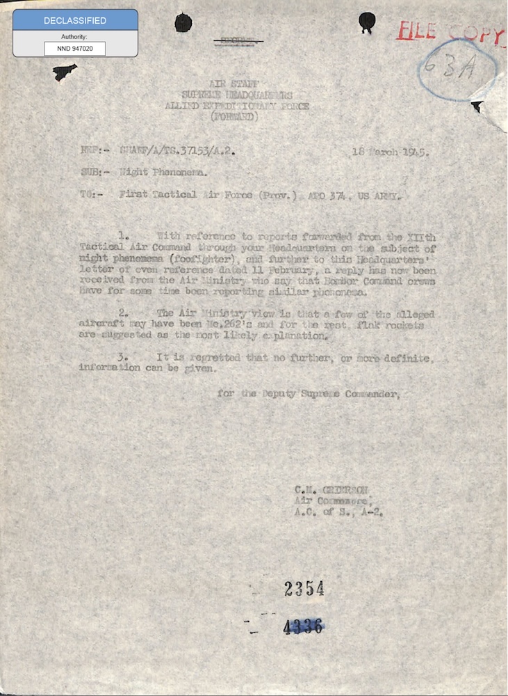
331_120752_Numeric_Files_1944–1945_37153_German_Armament_Equipment_Documents
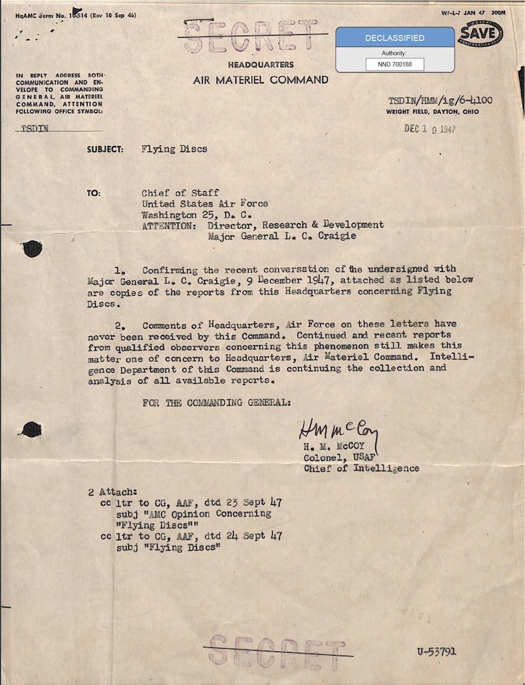
18_100754_ General 1946-7_Vol_2

DOW-UAP-D099, Nachrichtendienstliche Auswertung der „Geisterraketen“-Vorfälle, 1947
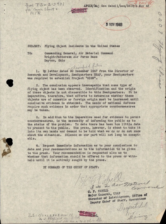
DOW-UAP-D100, Bericht des Air Materiel Command über unidentifizierte Flugobjekte, 1947-1948

18_6369445_General_1948_Vol_1